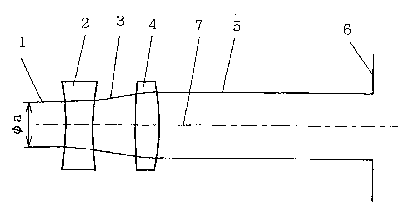
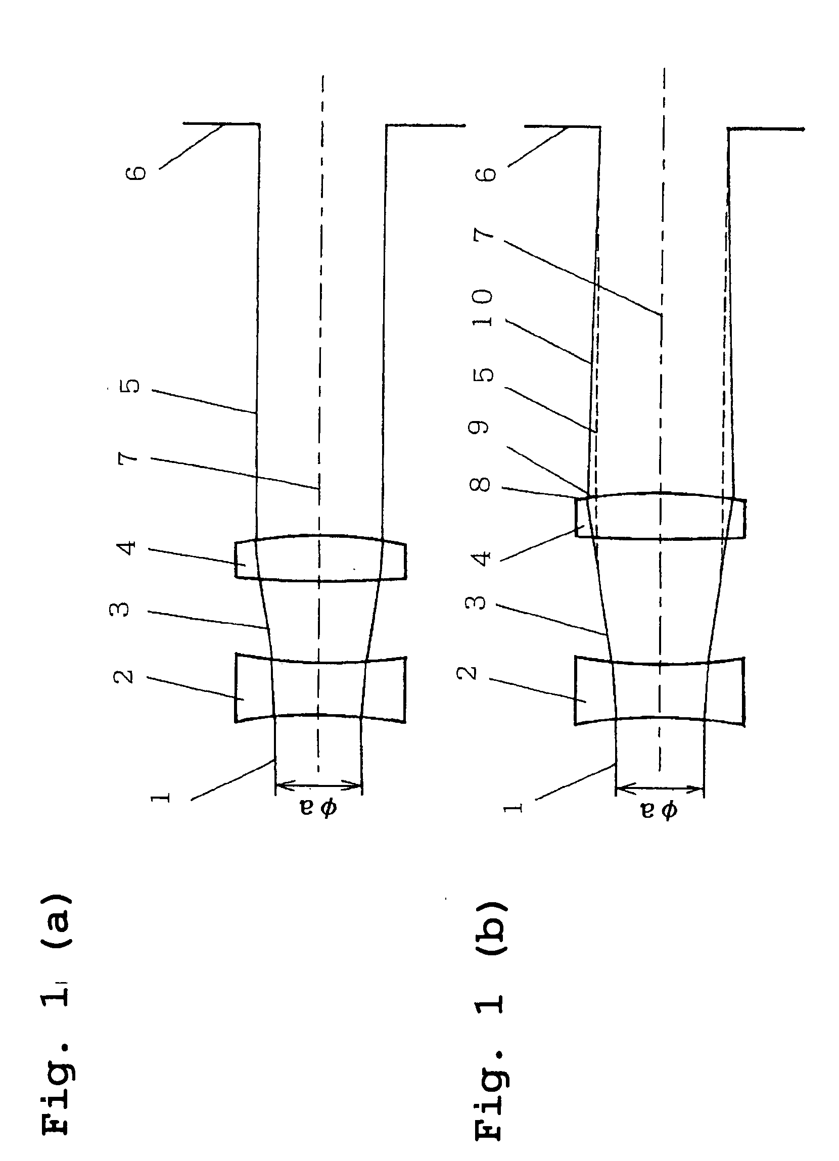
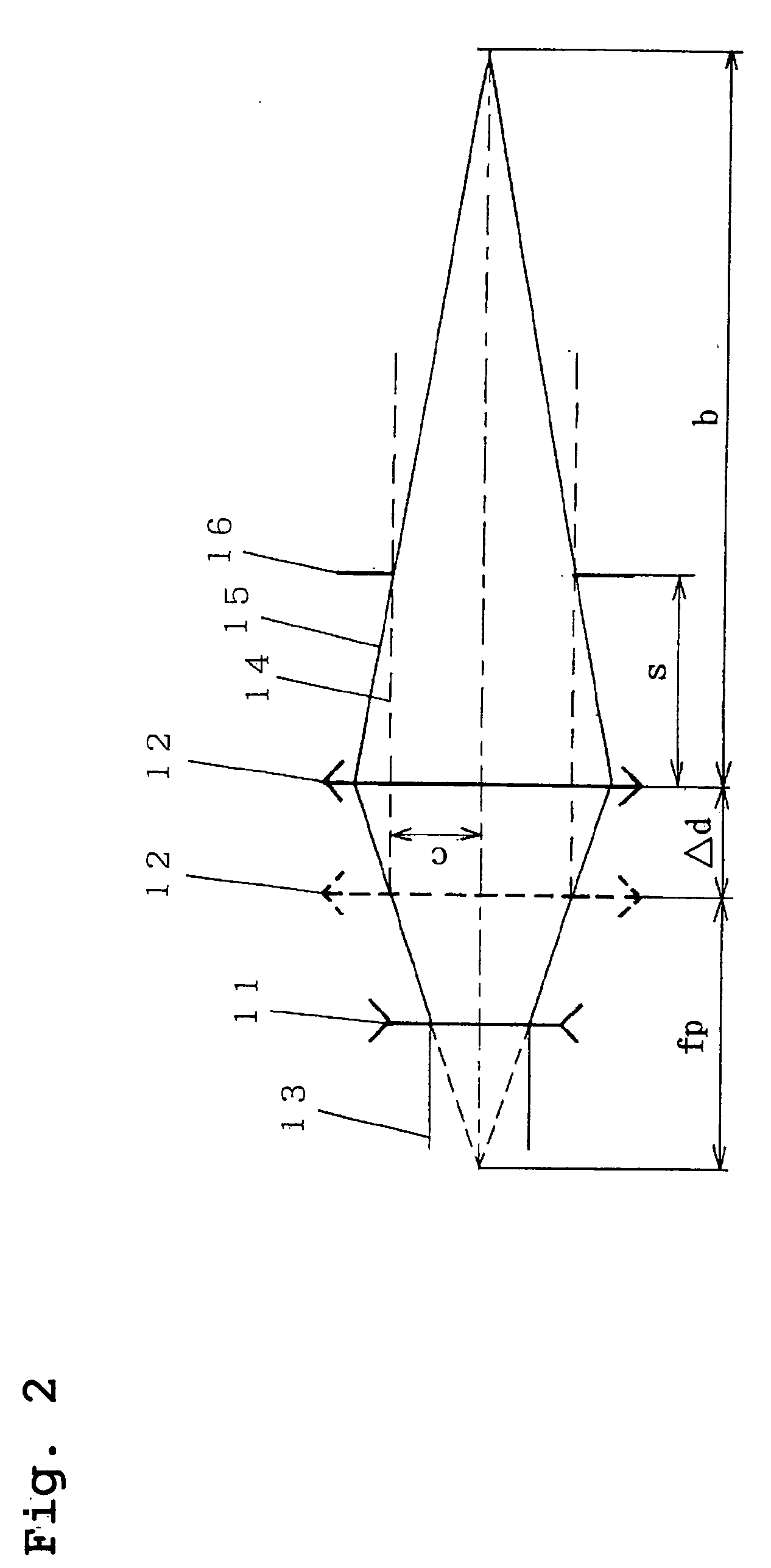
Optical head device and optical information recording and reproducing device
- Summary
- Abstract
- Description
- Claims
- Application Information
AI Technical Summary
Benefits of technology
Problems solved by technology
Method used
Image
Examples
Example
EXAMPLE 1
[0105] fp=10.0 [0106] R11=−8.48 [0107] R12=14.3 [0108] R21=33.2 [0109] R22=−9.02 [0110] E1=2.0 [0111] d1=1.2 [0112] d2=1.2 [0113] n1=1.74188 [0114] n2=1.71791 [0115] EFF=3.0
[0116] Here, since the focal length of the convex lens is 10 mm, the distance from the convex lens to the first surface of the objective lens is also set to 10 mm, assuming that the aperture of the objective lens lies in the first surface of the objective lens. See FIG. 3.
[0117] The amount of third-order spherical aberration corrected when the convex lens is moved by ±0.5 mm is about 0.18 λ: RMS. In the following description, when the convex lens is moved toward the light source, the amount of movement is designated as negative, and when the convex lens is moved toward the objective lens, the amount of movement is designated as positive.
[0118] The height of the light ray incident on the spherical aberration correcting optical system, which corresponds to the peripheral ray or marginal ray incident on th
Example
EXAMPLE 2
[0121] fp=20.0 [0122] R11=−23.11 [0123] R12=24.93 [0124] R21=81.09 [0125] R22=−12.036 [0126] E1=2.5 [0127] d1=1.2 [0128] d2=2.0 [0129] n1=1.74188 [0130] n2=1.52801 [0131] EFF=3.0
[0132] Here, since the focal length of the convex lens is 20 mm, the distance from the convex lens to the first surface of the objective lens is also set to 20 mm, assuming that the aperture of the objective lens lies in the first surface of the objective lens. See FIG. 4.
[0133] The amount of third-order spherical aberration corrected when the convex lens is moved by ±1.5 mm is about 0.15 λ: RMS. In the following description, when the convex lens is moved toward the light source, the amount of movement is designated as negative, and when the convex lens is moved toward the objective lens, the amount of movement is designated as positive.
[0134] The height of the light ray incident on the spherical aberration correcting optical system, which corresponds to the peripheral ray or marginal ray incident
Example
EXAMPLE 3
[0137] fp=8.0 [0138] R11=−6.914 [0139] R12=5.35 [0140] R21=71.645 [0141] R22=−4.414 [0142] E1=3.0 [0143] d1=0.8 [0144] d2=1.5 [0145] n1=1.75747 [0146] n2=1.52331 [0147] EFF=3.7
[0148] The second surface of the second lens is aspherical, and its aspherical shape is also expressed by (equation 1). See FIG. 5. [0149] k2=−0.1710231 [0150] A2, 4=2.839637×10⁻⁵
[0151] Here, since the focal length of the convex lens is 8 mm, the distance from the convex lens to the first surface of the objective lens is also set to 8 mm, assuming that the aperture of the objective lens lies in the first surface of the objective lens.
[0152] The amount of third-order spherical aberration corrected when the convex lens is moved by ±0.25 mm is about 0.25 λ: RMS. In the following description, when the convex lens is moved toward the light source, the amount of movement is designated as negative, and when the convex lens is moved toward the objective lens, the amount of movement is designated as positive.
PUM
 Abstract
Description
Claims
Application Information
 - R&D Engineer
- R&D Manager
- IP Professional
- Industry Leading Data Capabilities
- Powerful AI technology
- Patent DNA Extraction
Browse by: Latest US Patents, China's latest patents, Technical Efficacy Thesaurus, Application Domain, Technology Topic.
© 2024 PatSnap. All rights reserved.Legal|Privacy policy|Modern Slavery Act Transparency Statement|Sitemap


