System and methods for product and document authentication
- Summary
- Abstract
- Description
- Claims
- Application Information
AI Technical Summary
Benefits of technology
Problems solved by technology
Method used
Image

Examples
example 1
[0088] The detection of luminescent radiation, and the recording of steady state emission and excitation spectra, can be carried out using a Photon Technology International, Inc., QuantaMaster luminescence spectrometer, model SE-900M. Emission lifetimes can be measured using a PTI TimeMaster fluorescence lifetime spectrometer, equipped with GL-3300 nitrogen / dye laser as the excitation source (e.g. λexc-337 nm), a DG-535 delay / pulse generator and a strobe detector. Similar instruments, also capable of measuring luminescence decay times in the range from 100 ps to seconds are also available from other vendors (e.g. Edinburgh Analytical Instruments FS900 spectrofluorimeter system). These commercial instruments can be configured to record luminescence spectra and luminescence excitation spectra for the entire range of ultraviolet, visible and infrared wavelengths (e.g. 200-900 nm). Software available from the fluorimeter vendors is capable of decay time analysis including, for example,
example 2
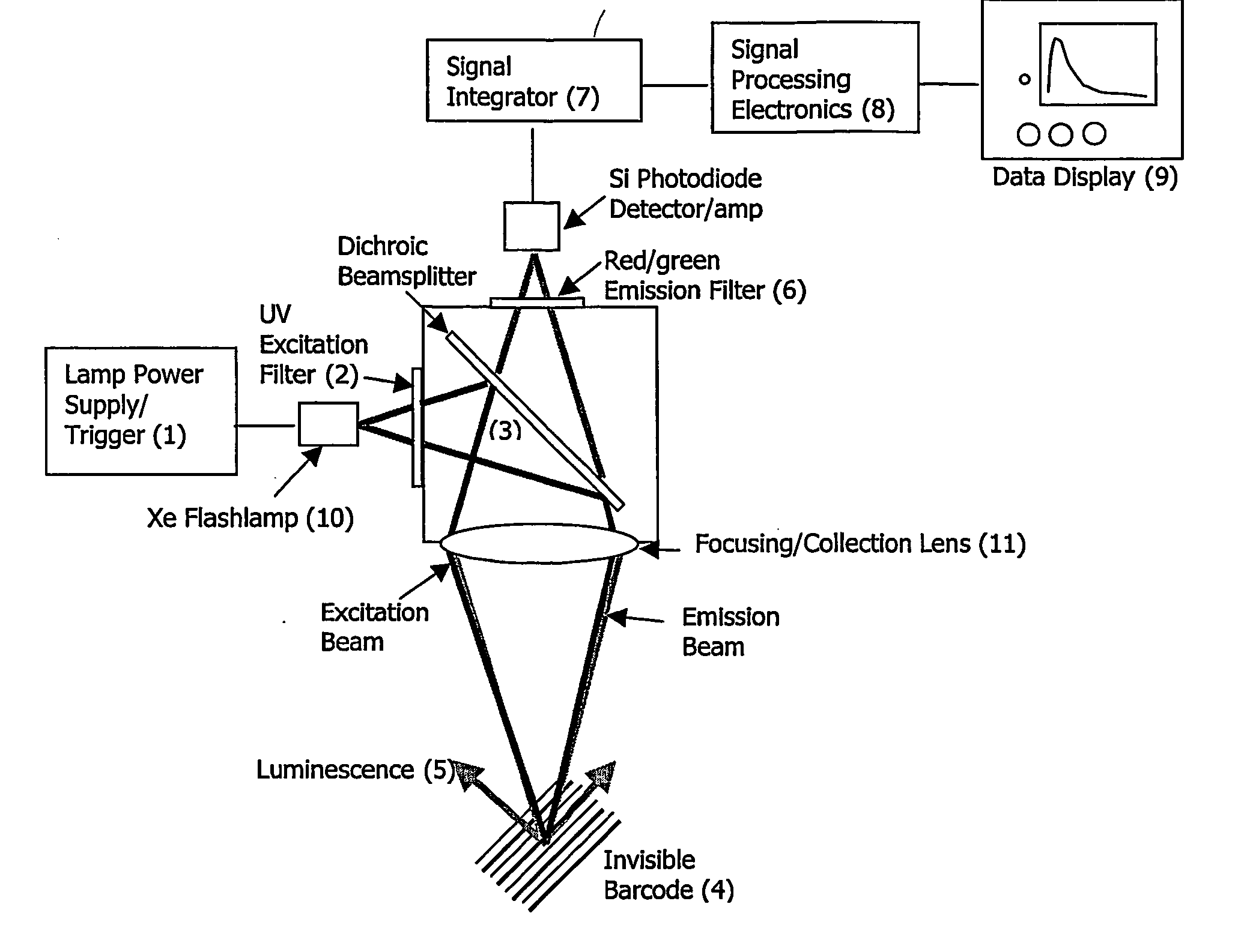
[0091] A specific embodiment of the invention has been developed as a prototype in a laboratory testbed environment. This embodiment is shown schematically in FIG. 7. A Xenon flashlamp is employed as a source of fast pulses of ultraviolet light. Using a technique similar to fluorescence microscopy, an excitation filter, dichroic beam splitter, and emission filter are arranged to provide optimum matching of the dye spectral absorption and emission characteristics. In this common-path arrangement, a lens serves as a dual-purpose focusing and collecting optic. The prototype interrogated a proprietary dye that had been ink-jet printed on standard white paper as a covert bar code. This dye / ink formulation had the following properties. An aqueous 0.5 mM solution of a proprietary dye that emits strongly, peaking at 614 nm upon excitation with near UV light was combined with 10% v / v of the humectant, 1,5-pentanediol. This composition was used to fill an HP black / white ink jet cartridge a
example 3
[0093] Another embodiment of the invention has been prototyped in a handheld “yes / no” digital lifetime detector. This embodiment is shown schematically in FIG. 13. The device is intended to identify arbitrary marks (e.g., barcodes) that are based on the unique luminescent compounds (e.g., europium or terbium chelates) and chemistries described herein. This capability is enabled by specifically designed excitation and emission optics that are “tuned” to the bands of the luminescent compounds, and appropriate signal processing electronics that analyze the observed luminescent lifetime and compare against the known characteristic decays. The handheld prototype contains two separate channels (e.g., one for a europium chelate with peak emission at 615 nm, and another for a terbium chelate with peak emission at ca. 515 nm), which can simultaneously interrogate and analyze multiple, arbitrarily shaped covert marks.
[0094] The handheld prototype (FIG. 13) employs a cavity enclosure 6, shield
PUM
 Abstract
Description
Claims
Application Information
 - R&D Engineer
- R&D Manager
- IP Professional
- Industry Leading Data Capabilities
- Powerful AI technology
- Patent DNA Extraction
Browse by: Latest US Patents, China's latest patents, Technical Efficacy Thesaurus, Application Domain, Technology Topic.
© 2024 PatSnap. All rights reserved.Legal|Privacy policy|Modern Slavery Act Transparency Statement|Sitemap