Locking assembly for ballast housing

a technology of locking assembly and ballast housing, which is applied in the direction of electrical apparatus casing/cabinet/drawer, lighting support device, lighting and heating apparatus, etc., can solve the problems of difficult task, increased work difficulty, and weight of body support, and achieves quick and easy installation, simple installation process, and efficient installation process

Active Publication Date: 2005-09-22
HUBBELL INC
View PDF13 Cites 27 Cited by
  • Summary
  • Abstract
  • Description
  • Claims
  • Application Information

AI Technical Summary

Benefits of technology

The technical effect of this patented locking assembly is its ease-of-installation and simplicity compared to existing methods like bolting or welding.

Problems solved by technology

The technical problem addressed in this patent is the difficulty and inconvenience associated with installing conventional locking assemblies for lightweight ballasts due to the need for special tools like a depth tool or a longer socket wrench to fix the locking assembly. Additionally, current locking assemblies have limitations in terms of sealing against external factors like rainwater, humidity, debris, and damage caused by heavy loads.

Method used


Image

  • Locking assembly for ballast housing
  • Locking assembly for ballast housing
  • Locking assembly for ballast housing

Examples


Embodiment Construction

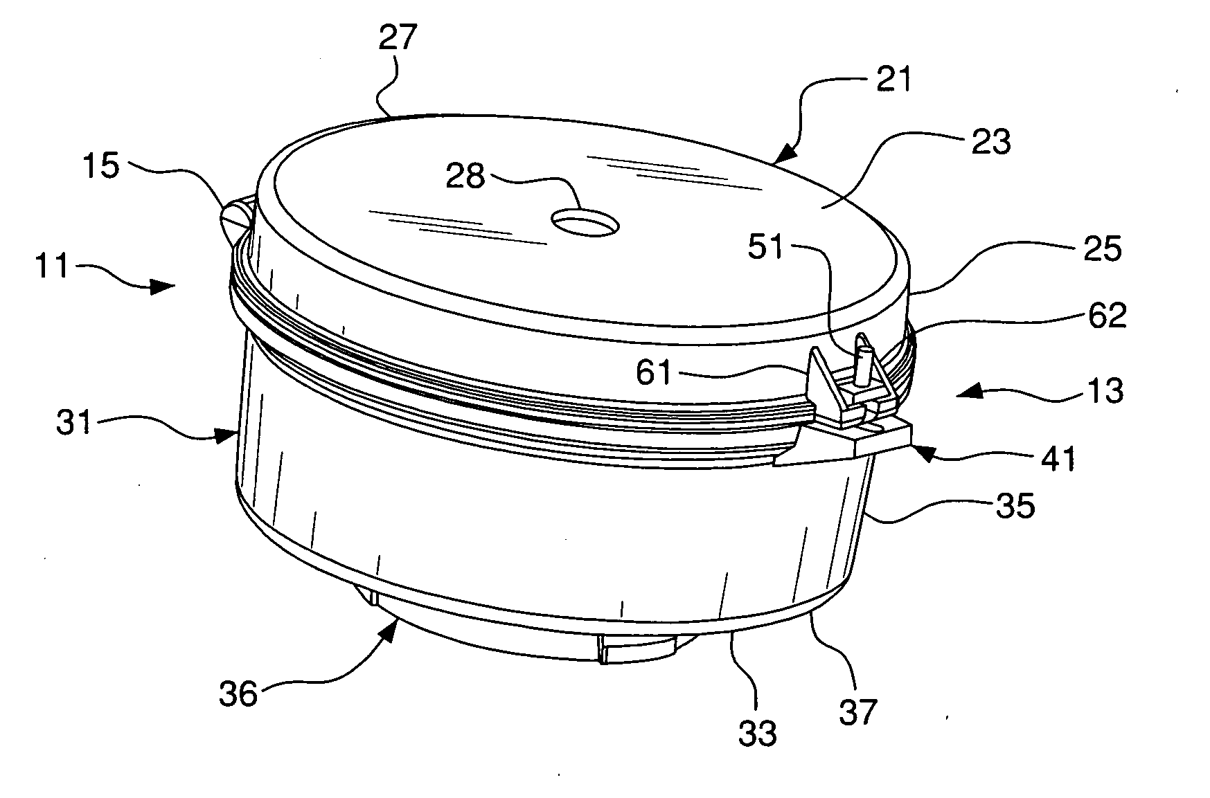
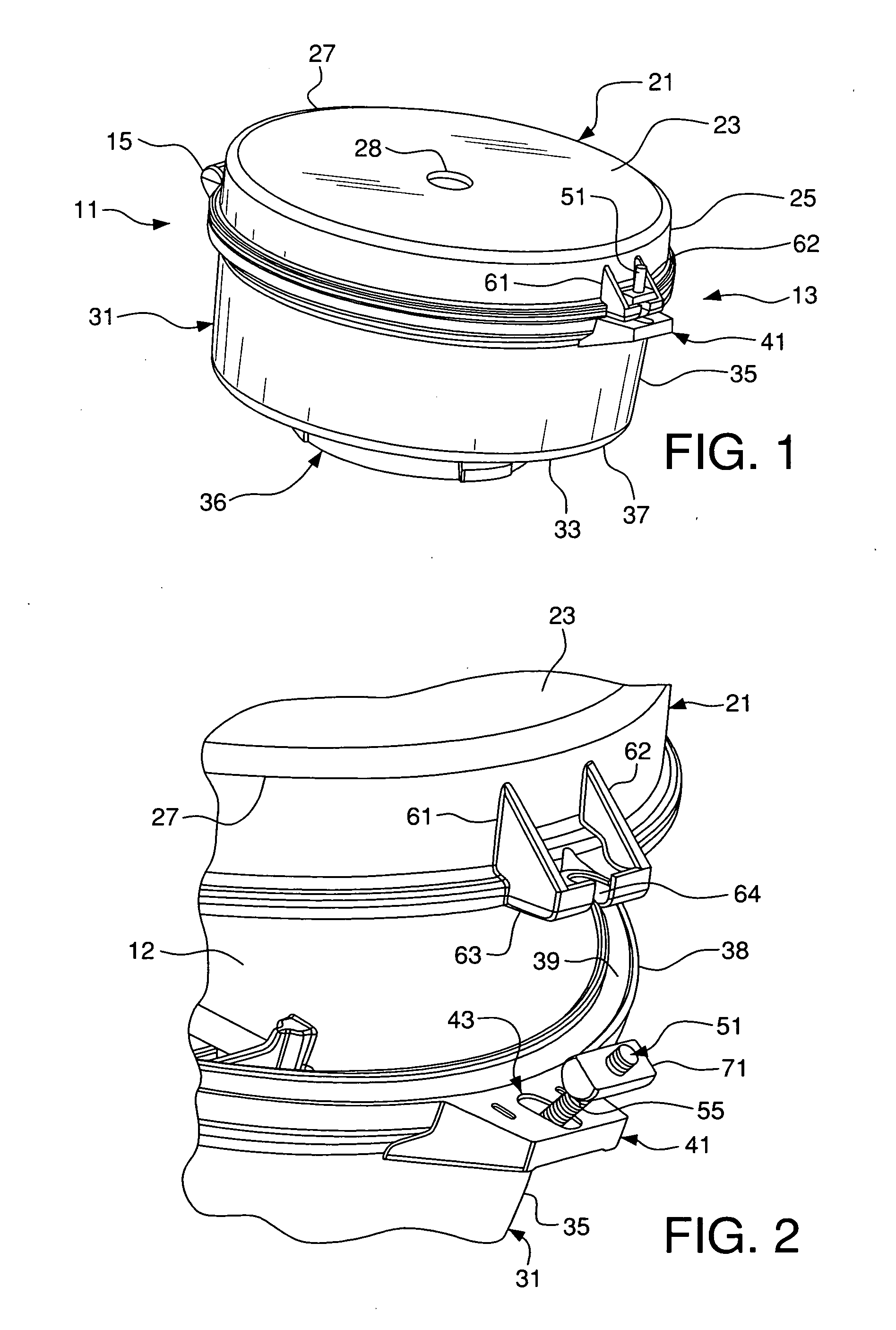
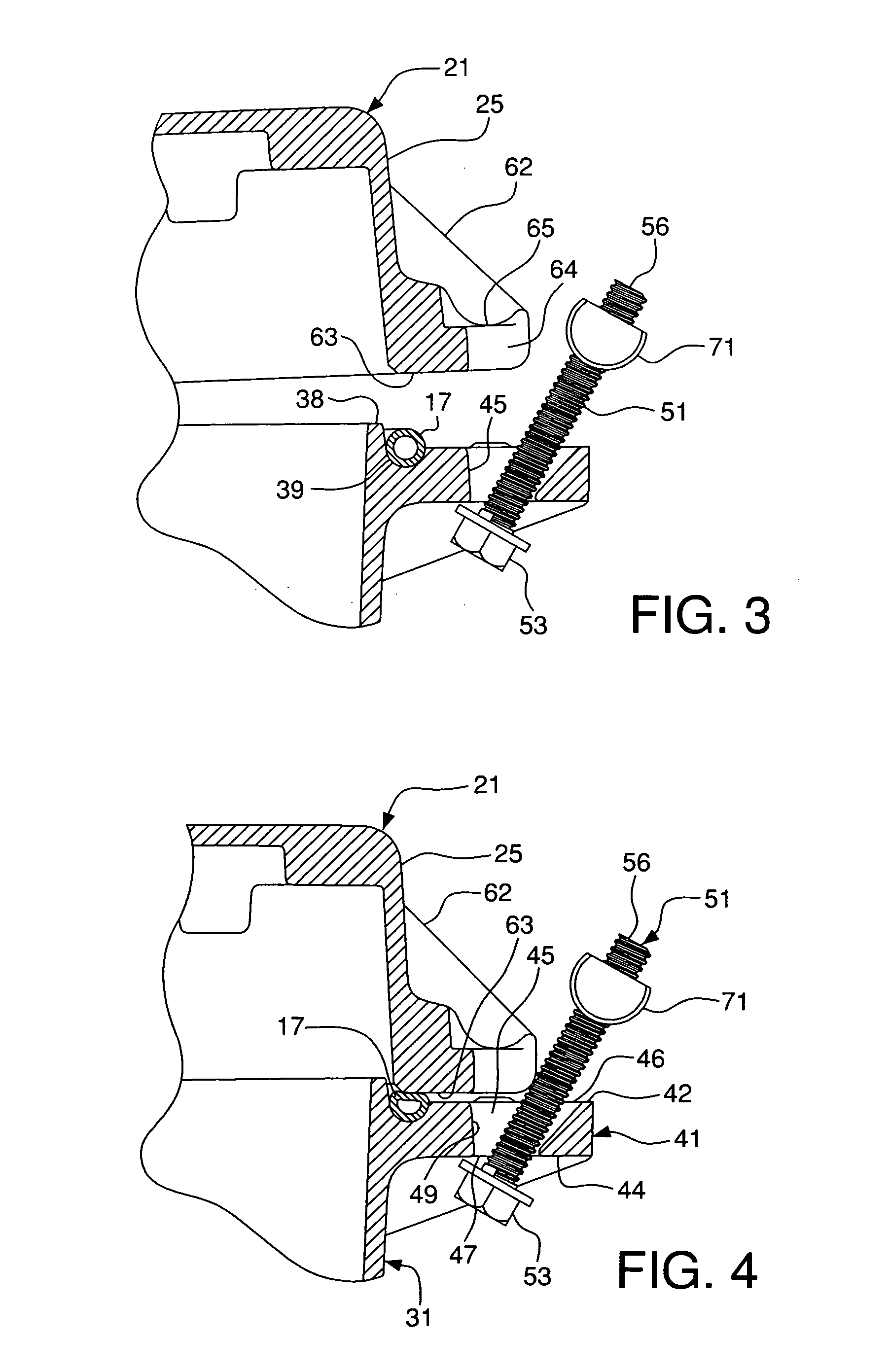
[0030] As shown in FIGS. 1-15, a locking assembly 13 for a ballast tank housing 11 simply and easily fastens a lid 21 to a body 31 of the ballast tank housing. The body 31 has a first base 33 and a first wall 35 extending upwardly from the first base. The lid 21 has a second base 23 and a second wall 25 extending downwardly from the second base. A tab 41 extends outwardly from the first wall 35. A fastener 51 is pivotally disposed in-an opening 43 in the tab 41. First and second ears 61 and 62 extend outwardly from the second wall 25. A third base 63 extends between the first and second ears 61 and 62, respectively. A slot 64 in the third base 63 is adapted to receive the fastener 51. A nut 71 is movably disposed on the fastener and is movable to a position adjacent the third base 33 to tightly secure the lid 21 to the body 31.

[0031] The ballast tank housing 11 has a lid (splice box or mounting hood) 21 and a body 31, as shown in FIG. 1. Preferably, the body and lid of the ballast hou


PUM


Abstract

A locking assembly for a ballast housing simply and easily locks a lid to a body of the housing. The body has a first base and a first wall extending upwardly from the first base. The lid has a second base and a second wall extending downwardly from the second base. A tab extends outwardly from the first wall. A fastener is pivotally disposed in an opening in the tab, and has a head adapted to receive a rotating device. A third base extends outwardly from the second wall. A slot in the third base is adapted to receive the fastener. A nut is threadably disposed on the fastener and the fastener is rotatable through the nut to engage the fastener head with the tab and to engage the nut with the base to tightly secure the lid to the body.

Description


Claims


Application Information

Patent Timeline
Owner HUBBELL INC
Why Eureka
Try Eureka