Grille for a cyclone vacuum

a vacuum cleaner and cyclone technology, applied in the field of vacuum cleaners, can solve the problems of reducing the dust-collection performance of the vacuum cleaner, and achieve the effect of improving the structure and preventing stagnant air regions

Inactive Publication Date: 2006-06-22
SAMSUNG GWANGJU ELECTRONICS CO LTD
View PDF2 Cites 13 Cited by
  • Summary
  • Abstract
  • Description
  • Claims
  • Application Information

AI Technical Summary

Benefits of technology

The invention relates to improving how well filters are used by cyclones or other devices for collecting particles from gases passing through them. It includes improvements made on existing structures to prevent areas where there can accumulate debris during operation without being blocked up with it effectively.

Problems solved by technology

This patented technical problem addressed in the patented describes how to improve the efficiency of removing small particles like tiny dirt during cyclonic separation processes such as separators and filters.

Method used


Image

  • Grille for a cyclone vacuum
  • Grille for a cyclone vacuum
  • Grille for a cyclone vacuum

Examples


Embodiment Construction

[0038] Exemplary embodiments of a grille member according to the present invention, a cyclone dust-collecting apparatus and a vacuum cleaner including such apparatus will now be described in greater detail with reference to the accompanying drawing figures.

[0039]FIG. 4 is a view schematically showing an upright vacuum cleaner 200 having a cyclone dust-collecting apparatus with a grille member according to an embodiment of the present invention.

[0040] As shown in FIG. 4, the upright vacuum cleaner 200 according to an exemplary embodiment of the present invention comprises a cleaner body 101 having vacuum suction means such as a vacuum motor installed therein, a suction brush 102 for drawing in dirt-laden air from a cleaning surface, and a cyclone dust-collecting apparatus 100 removably mounted in the cleaner body 101, for separating dirt from the intake air.

[0041] In this embodiment, the cleaner body 101 and the suction brush 102 are conventional, so detailed descriptions thereof are


PUM

PropertyMeasurementUnit
Angleaaaaaaaaaa
Angleaaaaaaaaaa
Angleaaaaaaaaaa

Abstract

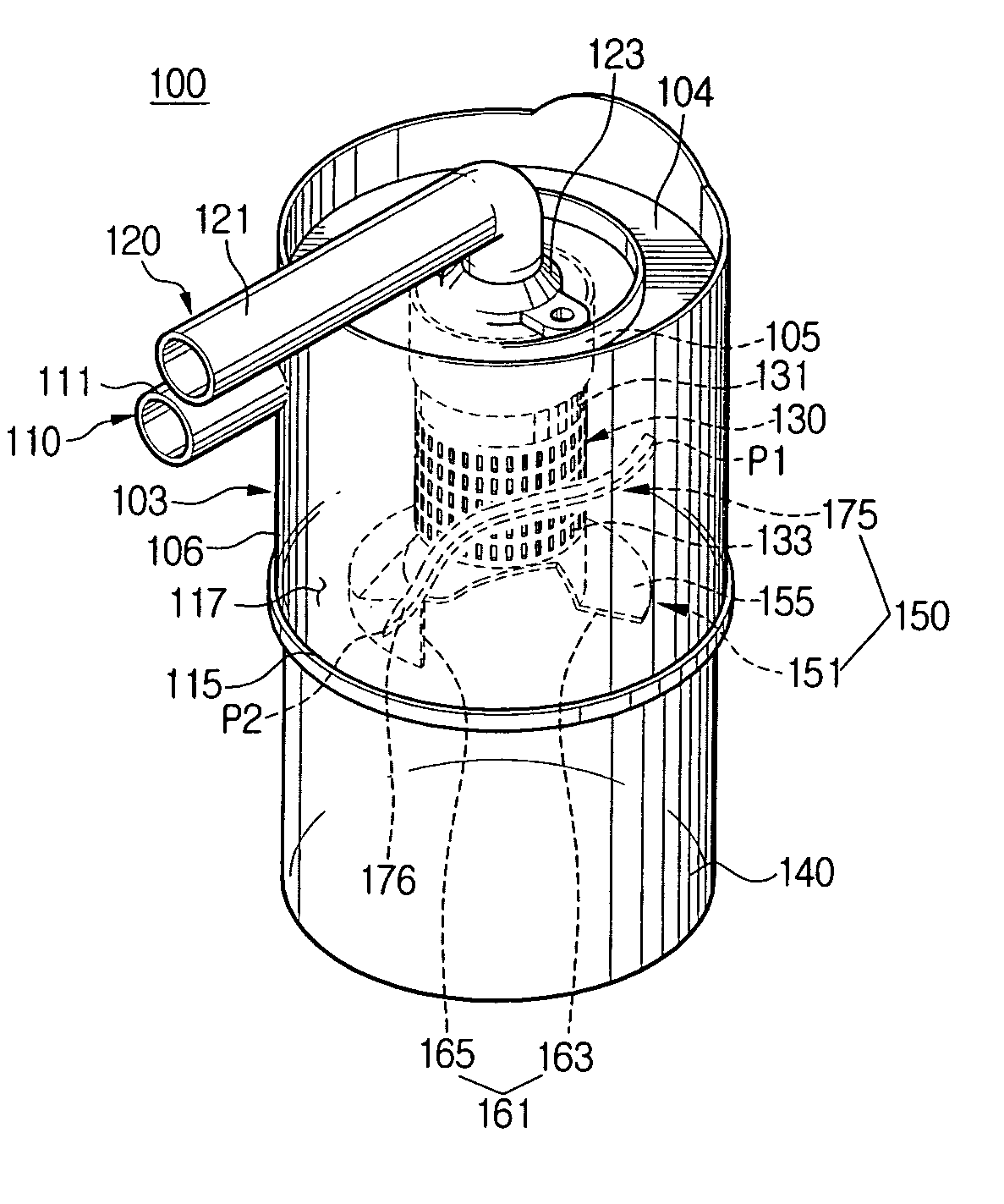
A grille member that can be used, for example, in a cyclone dust-collecting apparatus and a vacuum cleaner comprises a body around which a rotating current is formed, and a plurality of air passages formed at the body to guide the rotating current into the body. In an embodiment, the air passages have a leading surface facing toward a flow direction of the rotating air current and a tail surface upstream from the leading surface relative to the rotating air current, such that at least one plane extending along the tail surface and a line along the flow direction of the rotating air current meet at an obtuse angle. In this way, stagnant vortices are not generated in the vicinity of the tail surfaces of the air passages, and dust and the like do not accumulate in the vicinity of the tail surfaces of the air passages when dirt is centrifugally separated from drawn-in air by the rotating current.

Description


Claims


Application Information

Patent Timeline
Owner SAMSUNG GWANGJU ELECTRONICS CO LTD
Why Eureka
Try Eureka