Feed device for feeding molten metal in to a crystallizer

a technology of crystallizer and discharge device, which is applied in the direction of molten metal supplying equipment, molten metal conveying equipment, molten metal pouring equipment, etc., can solve the problems of the discharge device of the known art, the very carrying out of the process can be jeopardized, and the continuous casting of metal strips using counter-rotating rolls, etc., to reduce the kinetic energy of liquid steel pouring and the shape of the feed device is simple and compact

Inactive Publication Date: 2006-07-27
DANIELI & C OFF MEC SPA
View PDF11 Cites 1 Cited by
  • Summary
  • Abstract
  • Description
  • Claims
  • Application Information

AI Technical Summary

Benefits of technology

This patent describes a new type of equipment for producing liquid metal in a stable manner. It uses a special distributor with multiple tanks arranged at different locations along its length to create a uniform stream of liquid steel. By reducing the amount of energy needed by the process, it can produce more accurate castings faster than traditional methods.

Problems solved by technology

The technical problem addressed in this patent is how to improve the flow of metal through continuous casting without causing cracks or contamination in the final products produced due to uneven distribution of liquid metal in the ingot mold caused by the cooling operation.

Method used


Image

  • Feed device for feeding molten metal in to a crystallizer
  • Feed device for feeding molten metal in to a crystallizer
  • Feed device for feeding molten metal in to a crystallizer

Examples


Embodiment Construction

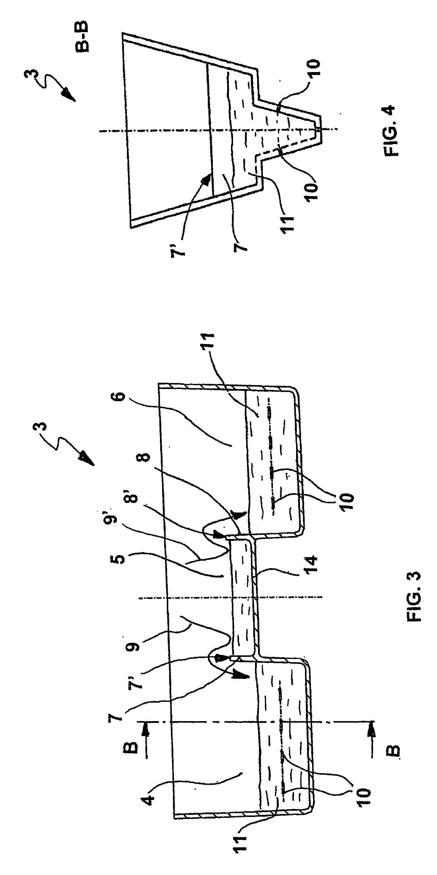
[0017] With reference to the figures, described herein is an embodiment of a feed device for feeding molten metal, in particular liquid steel, into an ingot mould for a continuous-casting machine with two crystallizer rolls. In particular, FIG. 1 shows a cross section according to a vertical plane parallel to the axis of the crystallizer rolls of parts of a continuous-casting machine, designated, as a whole, by the reference number 1, comprising the feed device according to the invention. In the remainder of the description, reference will be made to steel, but it is understood that the device can be adapted to the discharge of other metals for which the same casting technique is used.

[0018] The molten steel coming from a tundish, not represented in the figures, is poured, through a discharger 2, into a first distributor 3. The discharger 2 is substantially shaped like a funnel turned upside-down with the divergent section set downwards in the direction of the distributor 3, and has a


PUM

PropertyMeasurementUnit
Angleaaaaaaaaaa
Shapeaaaaaaaaaa

Abstract

A drop feeder (1) for feeding molten metal into an ingot mould (15) comprises a distributor (3) having a substantially prismatic shape, with one of the faces open, in which the inside of the distributor comprises three tanks (4, 5, 6), separated by walls (7, 8) functioning as weir for the molten melt poured into the intermediate tank (5). There are provided slots (10) arranged on the faces of the distributor (3) for emptying of the molten metal from the distributor into the ingot mould or into a second distributor.

Description


Claims


Application Information

Patent Timeline
Owner DANIELI & C OFF MEC SPA
Why Eureka
Try Eureka