Anisotropically conductive connector, production process thereof and application product thereof

Inactive Publication Date: 2006-08-10
JSR CORPORATIOON
View PDF14 Cites 5 Cited by
  • Summary
  • Abstract
  • Description
  • Claims
  • Application Information

AI Technical Summary

Benefits of technology

[0053] According to the present invention, since the molding material layer is subjected to a curing treatment in a state that the conductive particles present in the portion to become the part to be supported in the molding material layer have been retained in this portion by applying a magnetic field having high intensity to the portion to become the part to be supported, in the molding of an elastic anisotropically conductive film, the conductive particles present in the portion to become the part to be supported in the molding material layer, i.e., portions located above and below the inner peripheral edge portion about the through-hole in the frame plate are not gathered at the portion to become the conductive part for connection. As a result, it can be prevented that the conductive particles are contained in excess in the conductive parts for connection located most outside among the conductive parts for connection in the resulting anisotropically conductive film. Accordingly, a proper amount of the conductive particles can be contained in the respective conductive parts for connection, so that an anisotropically conductive connector having good conductivity at all the conductive parts for connection in the elastic anisotropically conductive film and necessary insulating property between adjacent conductive parts for connection is provided.
[0054] In addition, the conductive particles present in the portion to become the part to be supported in the molding material layer are oriented in the thickness-wise direction to form the elastic anisotropically conductive film having the conductive part for charge elimination in the part to be supported, whereby static electricity generated on the surface of the elastic anisotropically conductive film can be eliminated through the conductive part for charge elimination, so that it is prevented or inhibited that electric charges are accumulated on the surface of the elastic anisotropically conductive film. As a result, adverse influence by static electricity can be excluded.

Problems solved by technology

However, the anisotropically conductive elastomer sheet is flexible and easy to be deformed, and so it is low in handling property.
Therefore, the positioning and the holding and fixing of the uneven distribution type anisotropically conductive elastomer sheet are going to be difficult upon electrical connection between circuit devices and electrical connection to electrodes for inspection in electrical inspection of a circuit device.
In such a test, there is a problem that even when the necessary positioning, and holding and fixing of the circuit device to the uneven distribution type anisotropically conductive elastomer sheet has been realized once, the state of electrical connection is changed, and the stably connected state is not retained when they are subjected to thermal hysteresis by temperature change, since the degrees of stress by thermal expansion and heat shrinkage are different between a material making up the circuit device as the object of the inspection and a material making up the uneven distribution type anisotropically conductive elastomer sheet.
According to such an anisotropically conductive connector, it is hard to be deformed and easy to handle because the anisotropically conductive elastomer sheet is supported by the metal-made frame plate.
However, it has been found that such an anisotropically conductive connector involves the following problems.
However, the content of the conductive particles in any other conductive part, for example, the conductive part formed at the conductive part-forming portion X becomes too low, so that good conductivity cannot be achieved at such a conductive part.
Accordingly, an insulating part of quite large region is present at the peripheral portion of the anisotropically conductive elastomer sheet, therefore, the surface of the peripheral portion of the anisotropically conductive elastomer sheet is charged with static electricity according to the manner of use and service environment of the anisotropically conductive connector to cause various problems.
When the static electricity is discharged through the conductive parts of the anisotropically conductive elastomer sheet, not only the conductive parts of the anisotropically conductive elastomer sheet and a wiring circuit of the circuit board for inspection, but also the circuit devices as objects of the inspection are adversely affected.
As a result, there is a possibility that anisotropically conductive elastomer sheet and circuit board for inspection may be damaged, or the circuit device to be inspected as the object of the inspection may be broken.
In addition, when electric charges are accumulated on the surface of the anisotropically conductive elastomer sheet to charge the surface with static electricity, the circuit device to be inspected sticks to the anisotropically conductive elastomer sheet, so that it is difficult to smoothly conduct the inspecting operation.

Method used


Image

  • Anisotropically conductive connector, production process thereof and application product thereof
  • Anisotropically conductive connector, production process thereof and application product thereof
  • Anisotropically conductive connector, production process thereof and application product thereof

Examples


Example

EXAMPLE 1

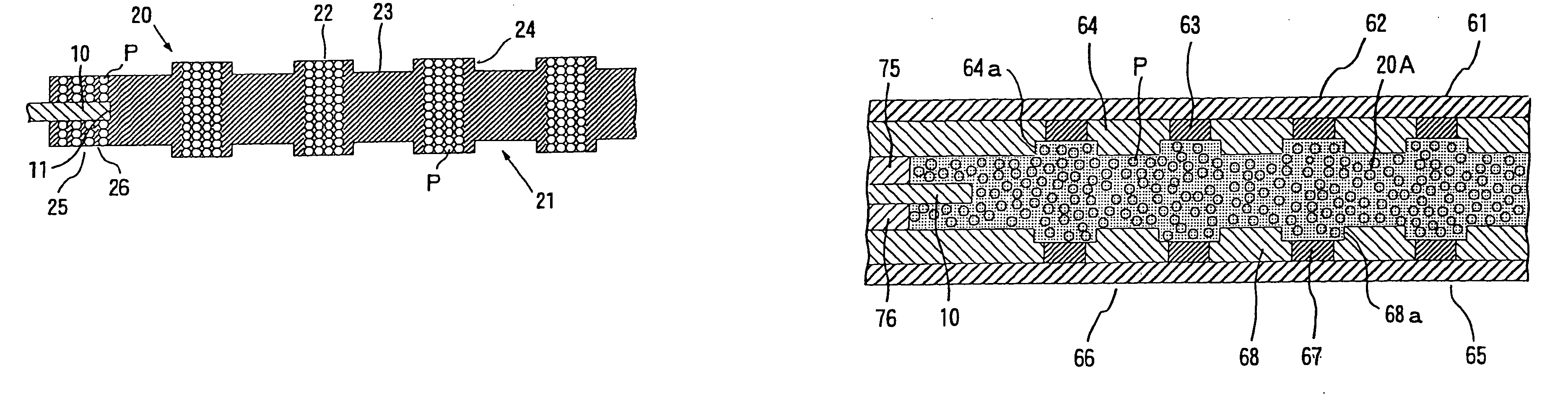
[0203] A frame plate, a mold for molding elastic anisotropically conductive films and a spacer for molding were produced in accordance with the following respective conditions.
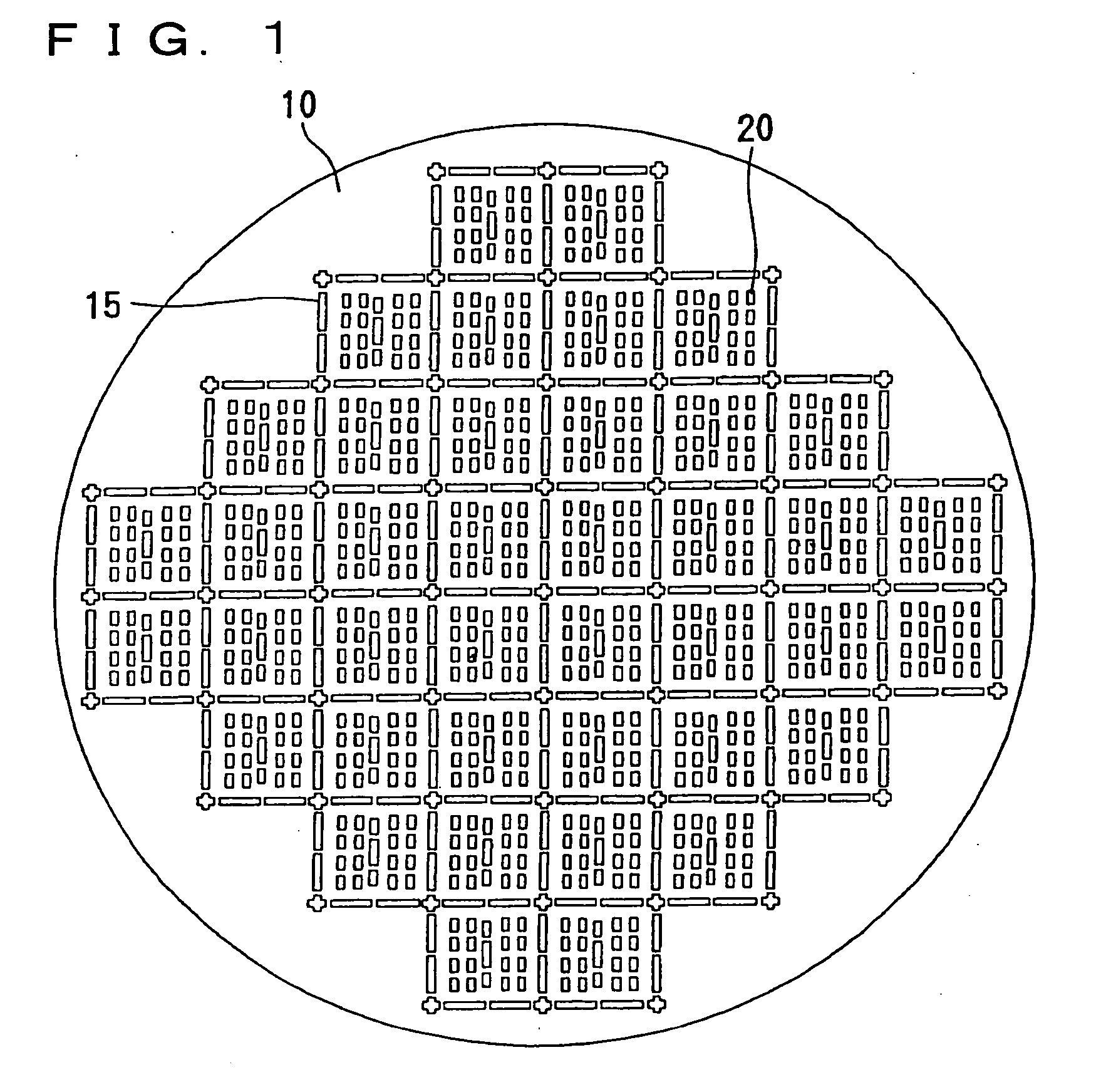
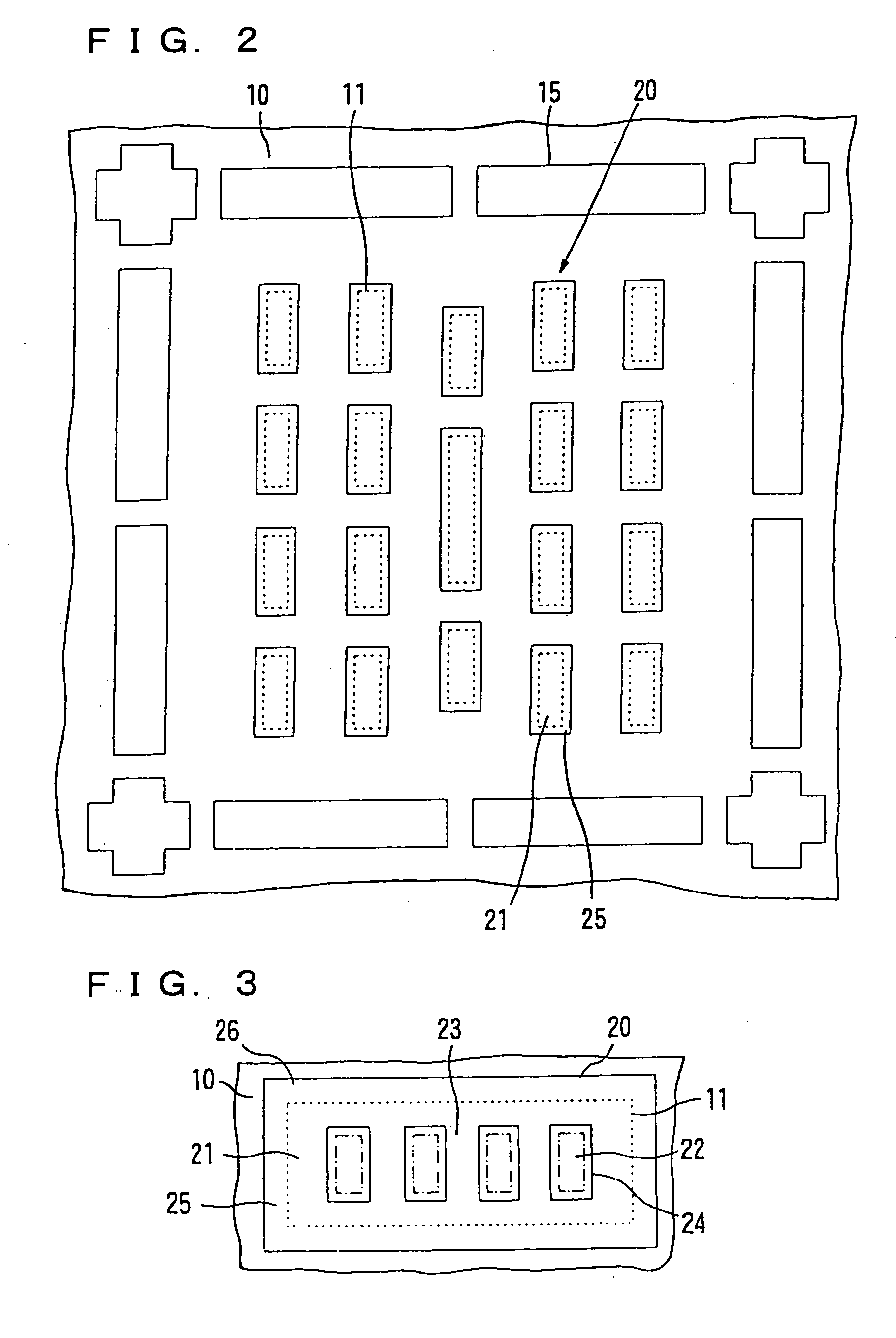
[Frame plate (10)]

Material:

[0204] Covar (saturation magnetization: 1.4 Wb / m2), thickness: 0.4 mm, size of through-hole (11): 16 mm×16 mm (sectional area S1 in the plane direction: 2.56 cm2)

[Mold (60)]

Base plates (62, 66):

[0205] Material: iron, thickness: 6 mm;

Ferromagnetic substance layers (63, 67):

[0206] Material: nickel, size: diameter: 1 mm (circular form), thickness: 0.1 mm, arrangement pitch (center distance): 2 mm, number of ferromagnetic layers: 64 layers (8×8 layers);

Non-magnetic substance layers (64, 68):

[0207] Material: that obtained by subjecting a dry film resist to a curing treatment, size of recesses (64a, 68a): diameter: 1.1 mm (circular form), depth: 0.4 mm, thickness of other portions than the recess: 0.5 mm (thickness of the recess: 0.1 mm).

[Spacers (75, 76) for moldi

Example

EXAMPLES 2 to 4

[0215] Respective anisotropically conductive connectors were produced in the same manner as in Example 1 except that frame plates (10), molds (60) and spacers (75, 76) for molding were produced in accordance with their corresponding conditions shown in Table 1, and these frame plates (10), molds (60) and spacers (75, 76) for molding were used to form each elastic anisotropically conductive film (20). The total volume of the conductive particles in the molding material layer, the size of the elastic anisotropically conductive film (20), and the like are shown in Table 2.

[0216] The proportions of the conductive particles contained in the conductive parts (22) for connection and the part (25) to be supported in the elastic anisotropically conductive film (20) of each of the anisotropically conductive connectors thus obtained were investigated. As a result, the contents were 35% in terms of a volume fraction for the conductive parts (22) for connection and 10% for the part

Example

COMPARATIVE EXAMPLES 1 to 4

[0219] Respective anisotropically conductive connectors were produced in the same manner as in Examples 1 to 4 except that the material of the frame plate (10) was changed to SUS304 (saturation magnetization: 0.01 Wb / m2).

[0220] The parts (25) to be supported in the elastic anisotropically conductive films (20) of the anisotropically conductive connectors thus obtained were observed. As a result, it was confirmed that the conductive particles were scarcely present in all the parts (25) to be supported.


PUM


Abstract

Disclosed herein are an anisotropically conductive connector, by which positioning, and holding and fixing to a circuit device can be conducted with ease even when the pitch of electrodes of the circuit device to be connected is small, and moreover good conductivity can be achieved as to all conductive parts, and insulating property between adjacent conductive parts can be surely achieved, a production process thereof, and applied products thereof. The anisotropically conductive connector is obtained by forming a molding material layer for the elastic anisotropically conductive film with conductive particles exhibiting magnetism dispersed in a liquid polymeric substance-forming material, which will become an elastic polymeric substance by a curing treatment, within the through-hole in the frame plate and at the inner peripheral edge portion about the through-hole of the frame plate, applying a magnetic field having higher intensity at a portion to become the conductive part for connection and a portion to become the part to be supported in the molding material layer, than any other portion, to the molding material layer, thereby gathering the conductive particles at the portion to become the conductive part for connection in a state that the conductive particles present in the portion to become the part to be supported have been retained in this portion, and orienting them in the thickness-wise direction, and subjecting the molding material layer to a curing treatment.

Description


Claims


Application Information

Patent Timeline
Owner JSR CORPORATIOON
Why Eureka
Try Eureka