Apparatus for controlling operation of compressors

a compressor and apparatus technology, applied in the field of compressors, can solve problems such as increasing costs and power consumption, and achieve the effect of reducing costs and power consumption

Inactive Publication Date: 2006-10-12
LG ELECTRONICS INC
View PDF4 Cites 17 Cited by
  • Summary
  • Abstract
  • Description
  • Claims
  • Application Information

AI Technical Summary

Benefits of technology

The technical effect of this patented device described in this patents allows one machine can be used on both types of machines without requiring expensive equipment or extra energy input from another unit. This means that it saves money while still being able to work effectively with different compression mechanisms.

Problems solved by technology

The technical problem addressed in this patents relates to improving the performance of a double acting type reciprocate compressor that controls its displacement during different stages of movement while reducing energy usage compared to traditional single action motions.

Method used


Image

  • Apparatus for controlling operation of compressors
  • Apparatus for controlling operation of compressors
  • Apparatus for controlling operation of compressors

Examples


Embodiment Construction

[0028] An apparatus for controlling an operation of compressors capable of reducing costs and power consumption by controlling two compressor applied to a refrigerator.

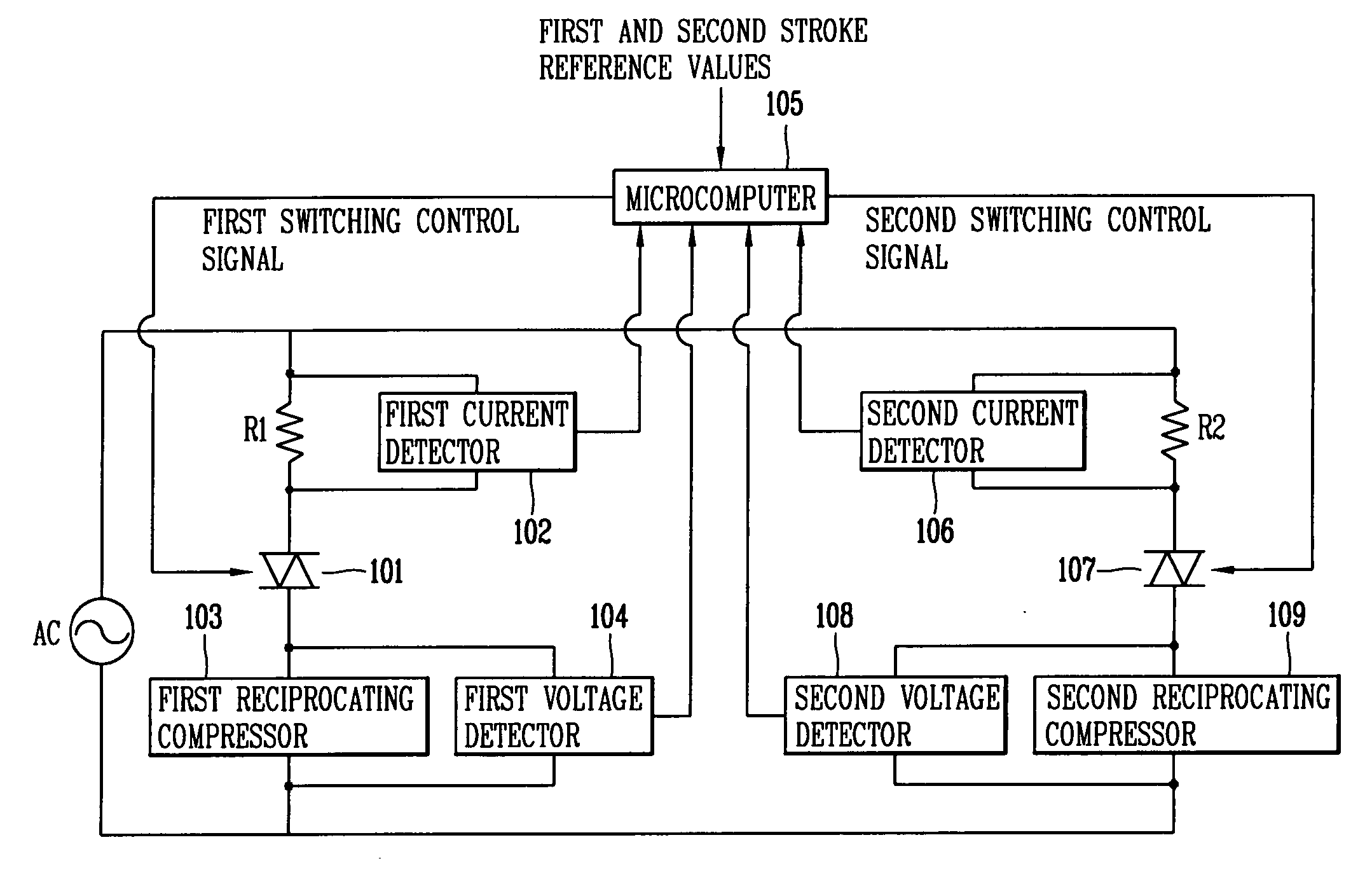
[0029]FIG. 3 is a block diagram showing the construction of a single apparatus for controlling an operation of two reciprocating compressors applied to a refrigerator in accordance with the present invention.

[0030] As shown in FIG. 3, the apparatus for controlling an operation of the compressors in accordance with the present invention includes a first voltage detector 104 for detecting a voltage applied to a first reciprocating compressor 103 installed in a refrigerator; a second voltage detector 108 for detecting a voltage applied to a second reciprocating compressor 109 installed in the refrigerator; a first current detector 102 for detecting a current applied to the second reciprocating compressor 109; a second current detector for detecting a current applied to the second reciprocating compressor 109; a microcompu


PUM


Abstract

An apparatus for controlling an operation of compressors includes a single microcomputer for calculating stroke estimate values of multiple compressors based on voltage and current values applied to the multiple compressors, and generating a plurality of switching control signals for independently controlling a voltage applied to the multiple compressors based on the calculated stroke estimate values and pre-set stroke reference values; and switching devices each installed in the multiple compressors, for independently controlling the voltage applied to the multiple compressors according to the plurality of switching control signals. Since the reciprocating compressors are controlled by a single apparatus, costs and power consumption can be reduced.

Description


Claims


Application Information

Patent Timeline
Owner LG ELECTRONICS INC
Why Eureka
Try Eureka