Digital broadcasting reception device

a digital broadcasting and reception device technology, applied in the field of digital broadcasting reception devices, can solve the problems of increasing the cost, reducing the degree of freedom, and limiting the size and position of the substrate, so as to achieve the effect of reducing cost and high degree of freedom

Inactive Publication Date: 2006-10-26
ORION ELECTRIC CO LTD
View PDF5 Cites 2 Cited by
  • Summary
  • Abstract
  • Description
  • Claims
  • Application Information

AI Technical Summary

Benefits of technology

This patented technology allows for flexibility in designing a receiving device that can handle multiple types of materials with varying mountings on a single housing. It also reduces costs by allowing for more options for components within the device.

Problems solved by technology

The technical problem addressed in this patent is how to provide an improved design that can effectively protect against unwanted electrical interference between different components within a digital circuit substrate while also reducing costs associated with manufacturing the substrate.

Method used


Image

  • Digital broadcasting reception device
  • Digital broadcasting reception device
  • Digital broadcasting reception device

Examples


Embodiment Construction

[0029] An embodiment as the best mode for implementing the present invention will be explained below with reference to FIG. 1 to FIG. 16. However, it goes without saying that the present invention is also easily applicable to modes other than that explained in the embodiment within a range not departing from the essence of the present invention.

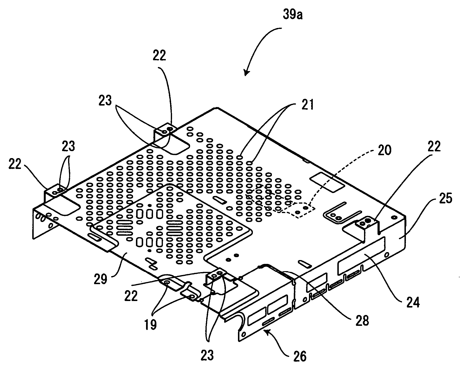
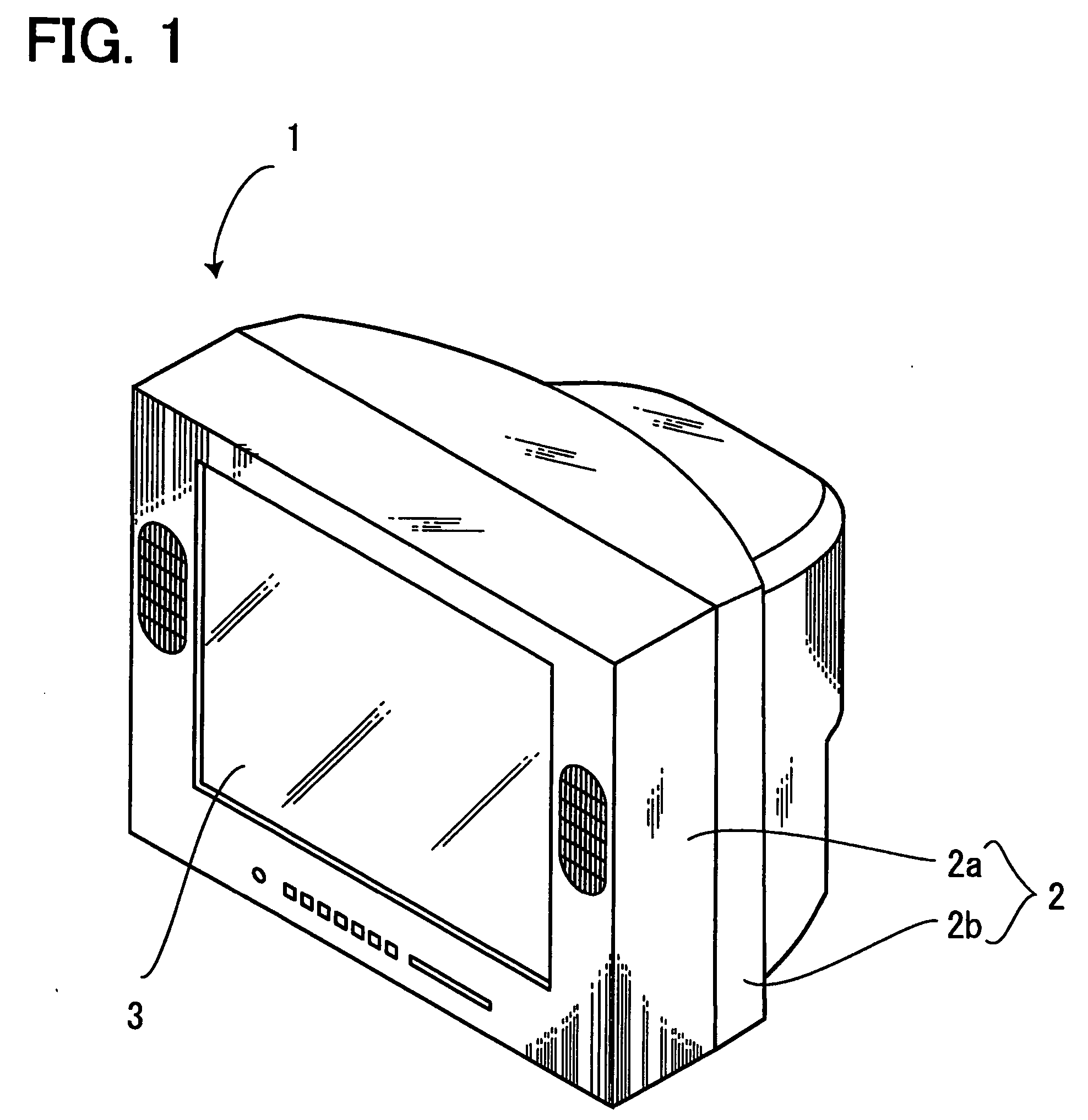
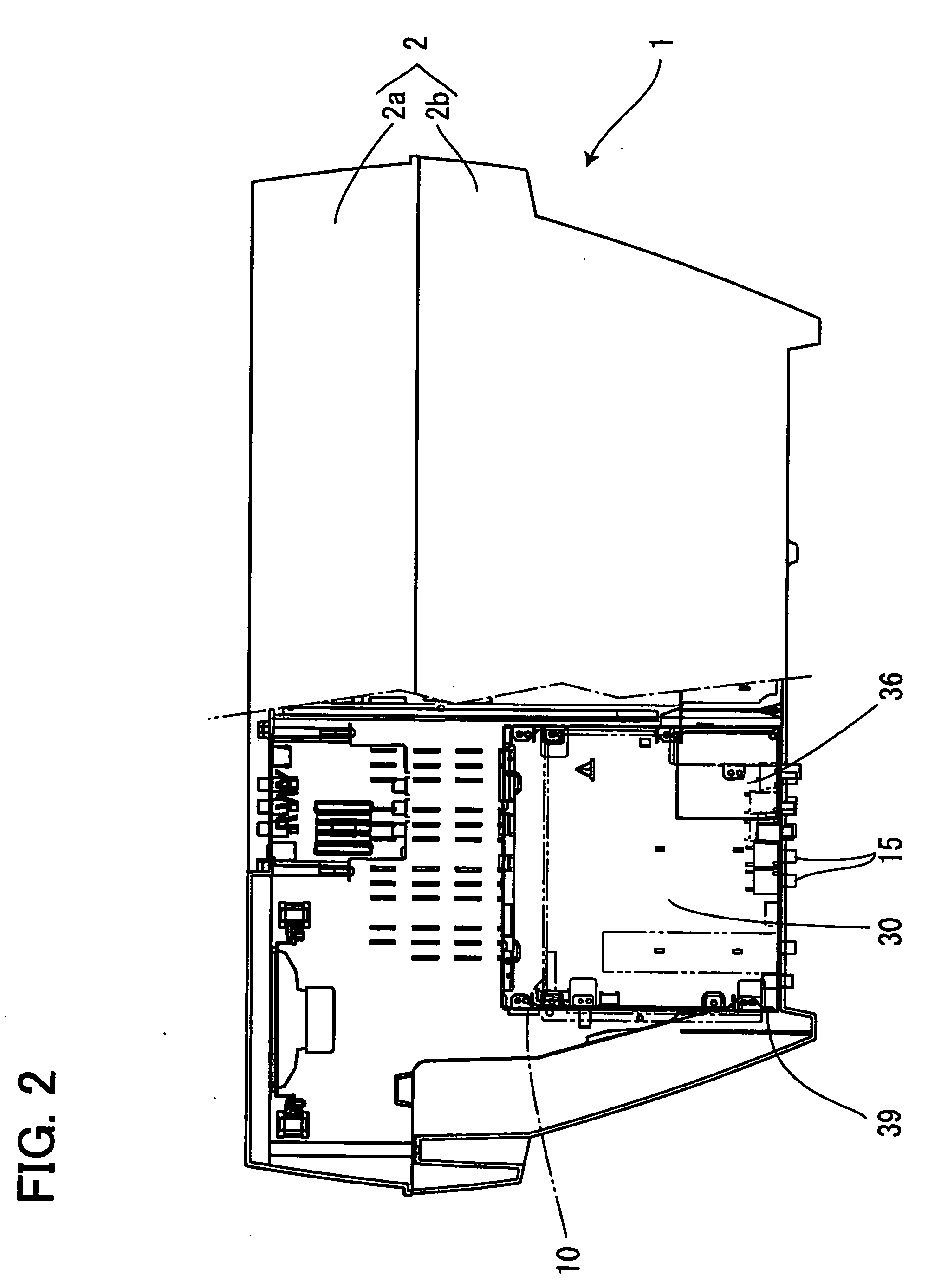
[0030]FIG. 1 is a perspective view of a digital television, FIG. 2 is a rear view of the digital television with the back cabinet removed, FIG. 3 is a rear view of main components of the digital television with the back cabinet removed, FIG. 4 is a perspective view of the top cover of the shielding case provided for the digital television, FIG. 5 is a section view of the top cover of the shielding case, FIG. 6 is a perspective view of the bottom cover of the shielding case, FIG. 7 illustrates the digital substrate loaded with a card slot mounted on the bottom cover, FIG. 8 is an exploded perspective view of the shielding case made up of the top


PUM


Abstract

A digital broadcasting reception device capable of accommodating a plurality of types of substrates having different mounting positions of parts in a common shielding case, having a higher degree of freedom and intended to reduce costs is provided. Inside a digital television is provided a metal shielding case wrapping around a substrate mounted with an electronic part and a detachable separation section in the shielding case. When accommodating a digital substrate having substantially the same size as that of this shielding case in the shielding case, the digital substrate is accommodated as is, and when a digital tuner mounted on the digital substrate which is smaller than this digital substrate exceeds the height of the shielding case, the digital tuner is placed at the position where the separation section is detached from the shielding case.

Description


Claims


Application Information

Patent Timeline
Owner ORION ELECTRIC CO LTD
Why Eureka
Try Eureka