Non-toxic liquid column sphygmomanometer

Inactive Publication Date: 2006-11-02
QDEVICE MEDICAL
View PDF31 Cites 1 Cited by
  • Summary
  • Abstract
  • Description
  • Claims
  • Application Information

AI Technical Summary

Benefits of technology

[0004] According to the invention there is provided a sphygmomanometer having an elongated tube, an air chamber coupled to a first end of the elongated tube, and a liquid chamber coupled to a second end of the elongated tube. The liquid chamber is partially filled with a liquid and coupled to a source of external pressure to be measured. A liquid offset section located p

Problems solved by technology

The only major problem is that mercury is one of the top three toxic elements on earth.
The health and environmental risks associated with mercury are very high.
Aneroid sphygmomanometers have not gained wide acceptance for diagnosis of hypertension

Method used


Image

  • Non-toxic liquid column sphygmomanometer
  • Non-toxic liquid column sphygmomanometer
  • Non-toxic liquid column sphygmomanometer

Examples


Embodiment Construction

[0057] In the following description like parts in the same or in different figures are referred to by the same reference numbers.

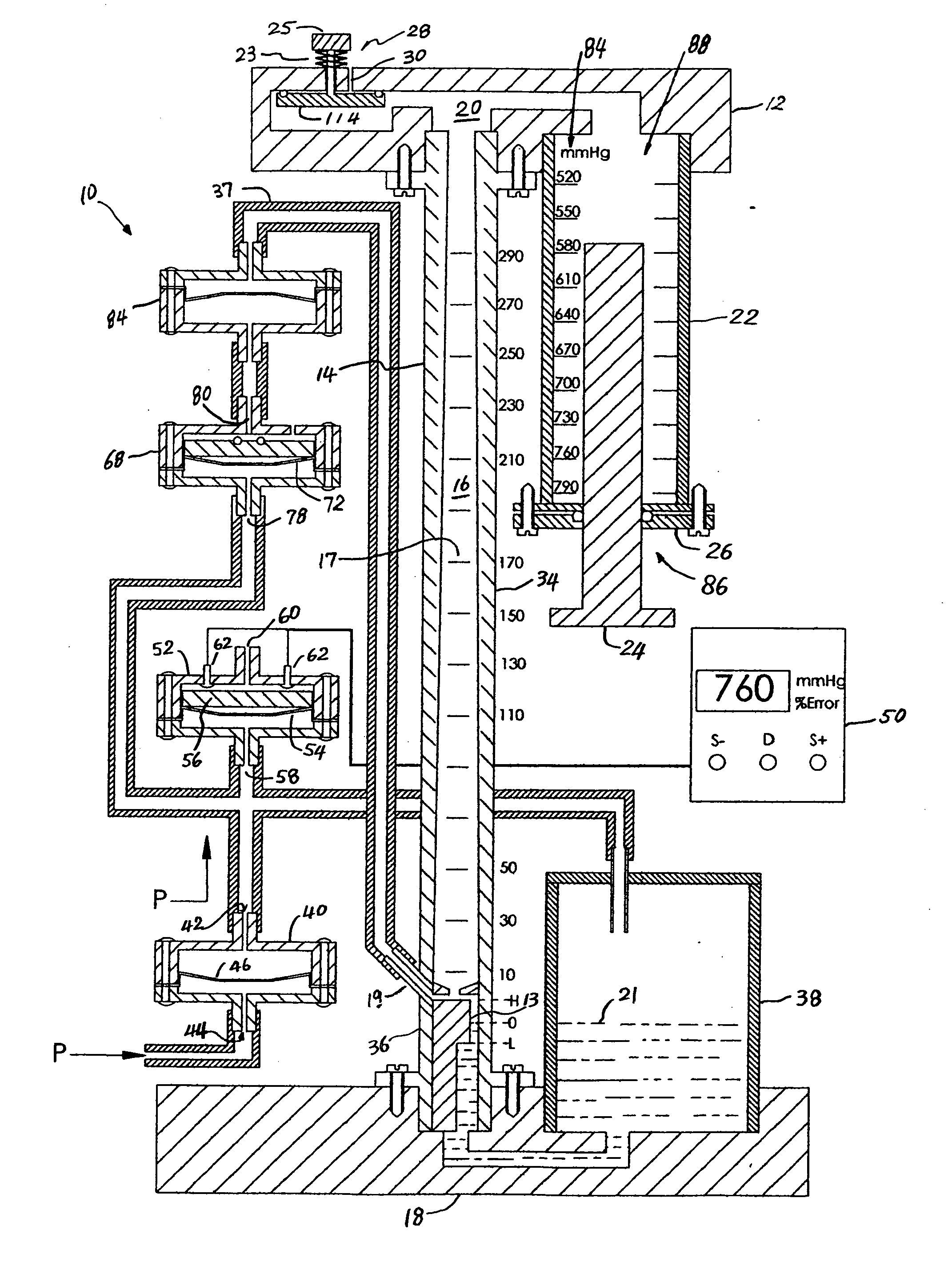
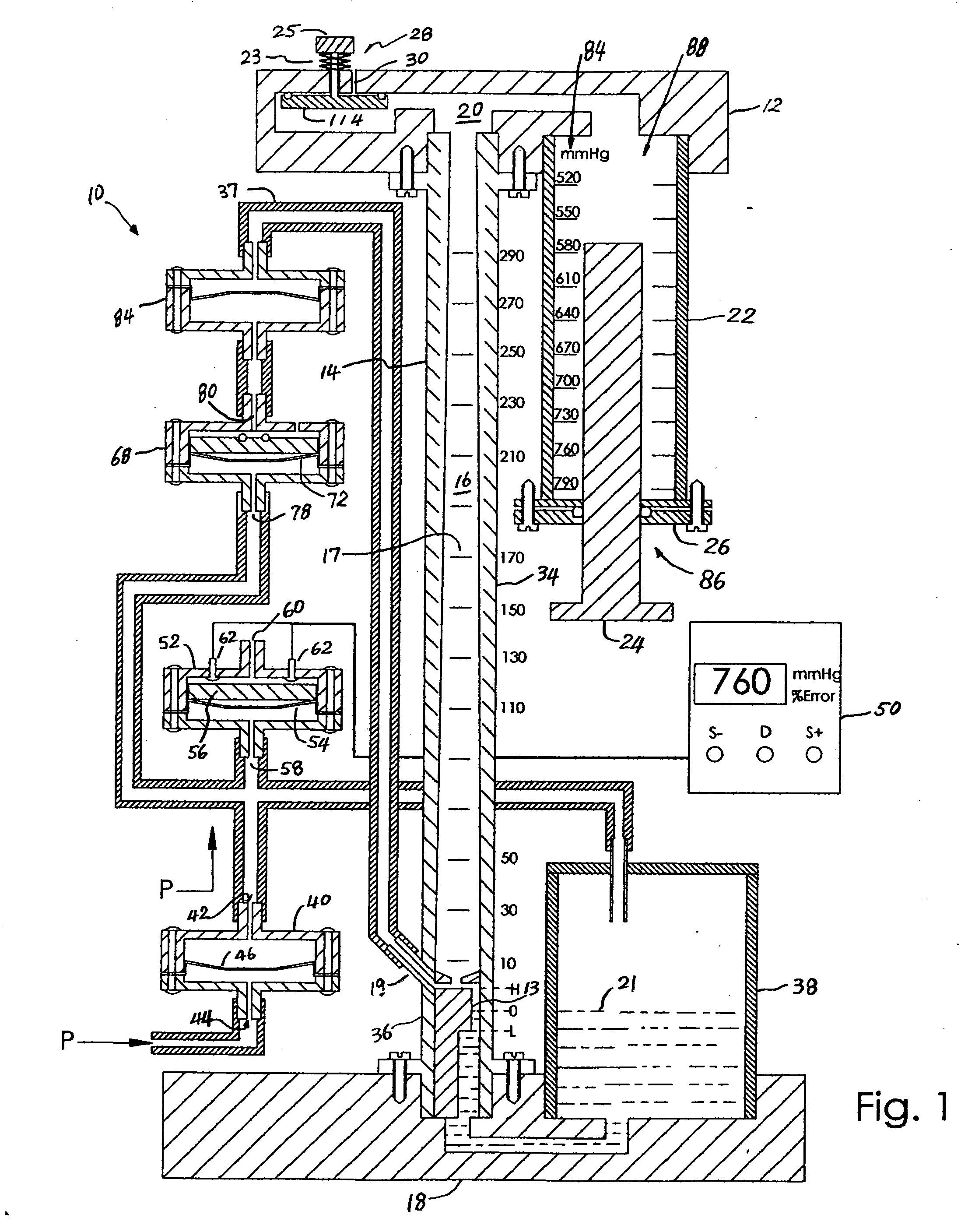
[0058] Referring to FIG. 1, a manometer 10 has top manifold 12 coupled to an upper end of an elongated tube 14. The lower end of the elongated tube 14 is coupled to a bottom manifold 18. The top manifold 12 has a plenum 20 interconnecting the fluid passageway 16 of the elongated tube 14 with an air chamber 22. An insert 24 passes through a bottom flange 26 of the air chamber 22 and is used to adjust the air volume in the air chamber 22 for installation at different altitudes. A manual ventilation valve 28 seals a bore 30 extending from atmosphere to the plenum 20. The manually operated ventilation valve 28 is normally biased closed by a bias spring 23 and opened by pressing a button 25 of the valve 28. A large disc with a large o-ring maximizes the sealing force exerted on the disc 114 by the pressure in the plenum to seal the bore 30 from the plenum 20.

[00


PUM


Abstract

A sphygmomanometer having an elongated tube, an air chamber coupled to a first end of the tube, and a liquid chamber coupled to a second end of the tube. The liquid chamber is partially filled with fluid and is couplable to a source of external pressure. An offset region located proximate the second end of the tube has a significantly reduced cross-sectional area so as to reduce the effect of fluid level changes on pressure measurement accuracy. At least one ventilation valve is coupled to the elongated tube and the air chamber and is operative to vent the elongated tube and the air chamber to atmosphere.

Description


Claims


Application Information

Patent Timeline
Owner QDEVICE MEDICAL
Why Eureka
Try Eureka