Medical body fluid metering and control system and metering method
A control system and body fluid technology, applied in other medical devices, suction containers, hypodermic injection devices, etc., can solve the problems of unable to measure the flow rate at the scheduled time, no total discharge statistics, inaccurate measurement, etc.
- Summary
- Abstract
- Description
- Claims
- Application Information
AI Technical Summary
Problems solved by technology
Method used
Image

Examples
no. 1 example
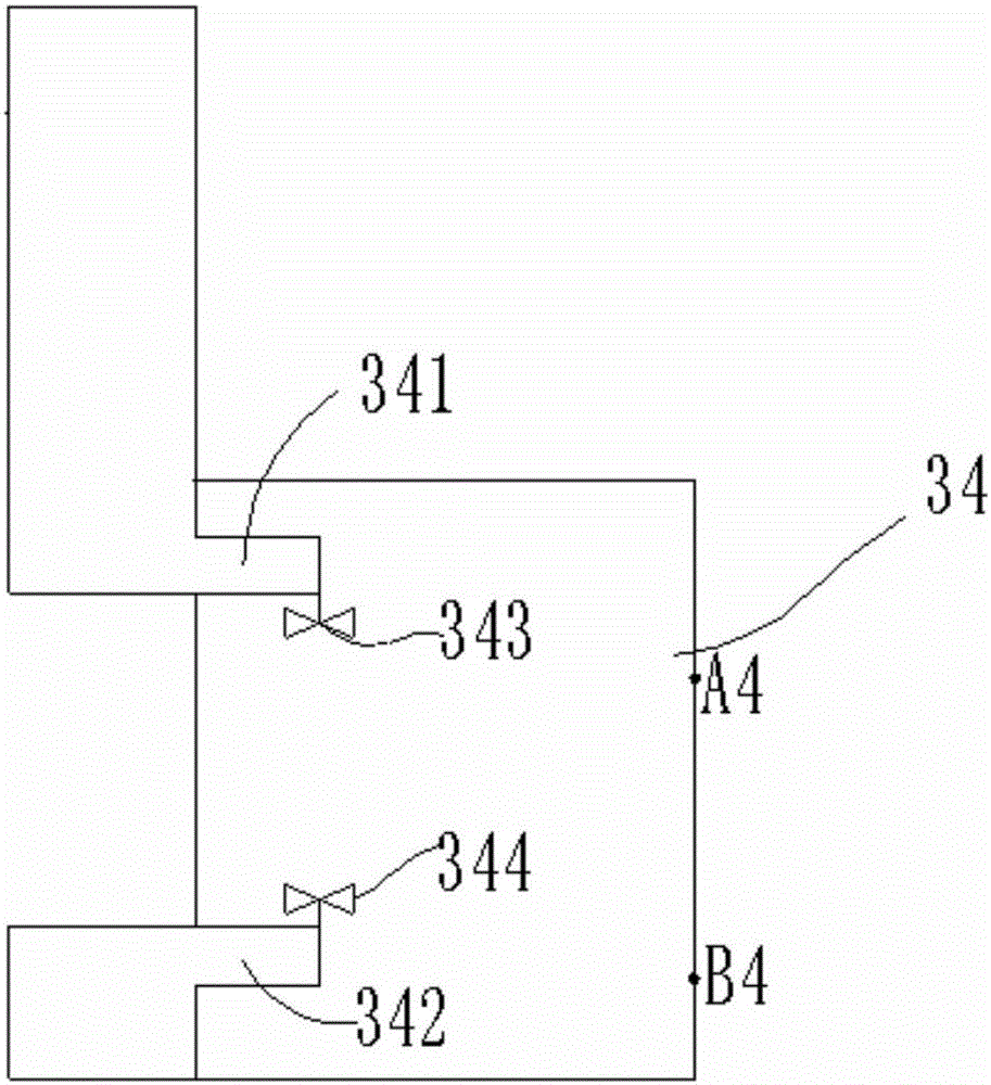
[0047] Such as image 3 As shown, a liquid inlet 341 and a liquid discharge 342 are provided on the side wall of the metering container 34, and the liquid control component is a solenoid valve. An upper solenoid valve 343 is installed on the liquid inlet 341, and a lower solenoid valve 344 is installed on the liquid discharge port 342, and the solenoid valve and the controller are connected through a circuit. The opening and closing of the liquid inlet and the liquid outlet are controlled by switching the solenoid valve. In the initial state, the upper electromagnetic valve is opened, and the lower electromagnetic valve is closed, so that the body fluid enters, and the metering container starts to enter the liquid. A liquid level sensing component A4 and a liquid level sensing component B4 are also arranged on the side wall of the metering container 34 . The specific process is that the body fluid enters the metering container through the liquid inlet, and when the liquid level
no. 2 example
[0049] Such as Pic 4-1 , 4-2As shown, the side wall of the metering container 35 extends horizontally out of the upper liquid inlet channel 351 and the lower liquid discharge channel 352, and a liquid level sensing part A5 and a liquid level sensing part B5 are arranged on the side wall of the metering container. An electromagnet 353 is arranged between the upper liquid inlet channel 351 and the lower liquid discharge channel 352 , and an electromagnetic coil 453 is wound on the outer wall of the electromagnet. A liquid inlet control plug 3531 is installed on the upper end of the electromagnet, and a liquid discharge control plug 3532 is installed on the lower end of the electromagnet. The electromagnet 353 is connected to the controller 451 through the drive circuit 452, so that the electromagnet 353 drives the inlet and outlet control plugs to move up and down. The liquid inlet control plug 3531 can be inserted into the upper liquid inlet channel 351 , and the liquid dischar
no. 3 example
[0053] Such as Figure 5-1 , 5-2 As shown, the metering container 36 is an upright cylinder with a liquid inlet 361 and a liquid discharge 362 on its side wall. The liquid control component is an electromagnet, and there is a plunger 364 inside the metering container 36. The two ends of the plunger 364 have annular flanges 3641 and 3642, wherein the annular flange 3642 can be made of an elastic tympanic membrane. The space between the two annular flanges is the unit volume. The control unit drives the plunger to slide up and down by controlling the two-way electromagnet or the one-way electromagnet combined with the spring return method, Figure 5-1 It is a one-way electromagnet plus spring return type, the lower part of the plunger is connected with the electromagnet, and the upper part of the plunger is connected with the spring. Of course, you can also Figure 5-3 As shown, the lower part of the plunger is connected to the spring, and the upper part of the plunger is conne
PUM
 Abstract
Description
Claims
Application Information
 - R&D Engineer
- R&D Manager
- IP Professional
- Industry Leading Data Capabilities
- Powerful AI technology
- Patent DNA Extraction
Browse by: Latest US Patents, China's latest patents, Technical Efficacy Thesaurus, Application Domain, Technology Topic.
© 2024 PatSnap. All rights reserved.Legal|Privacy policy|Modern Slavery Act Transparency Statement|Sitemap