Airfoil refurbishment method

Inactive Publication Date: 2007-02-01
LAGRAFF JOHN ROBERT +5
View PDF15 Cites 20 Cited by
  • Summary
  • Abstract
  • Description
  • Claims
  • Application Information

AI Technical Summary

Benefits of technology

[0017] Accordingly, one aspect of the present invention is to provide an airfoil refurbishment system that includes an environmentally

Problems solved by technology

However, materials from which an airfoil is made may limit the operating temperature.
In time, however, a coating degrades.
There are several disadvantages with current refurbishment.
One major disadvantage is that no integrated system exists for refurbishment.
As a general rule, there is a dearth of equipment at the turbine overhaul site for performing any of the number of steps of airfoil refurbishment, let alone an integrated system for all of the steps of refurbishment.
As a turbine often is located in a first country, the first remote location is in a second country, and the second remote loca

Method used


Image

  • Airfoil refurbishment method
  • Airfoil refurbishment method
  • Airfoil refurbishment method

Examples


Embodiment Construction

[0046] In the following description, like reference characters designate like or corresponding parts throughout the several views. Also in the following description, it is to be understood that such terms as “forward,”“rearward,”“left,”“right,”“upwardly,”“downwardly,” and the like are words of convenience and are not to be construed as limiting terms.

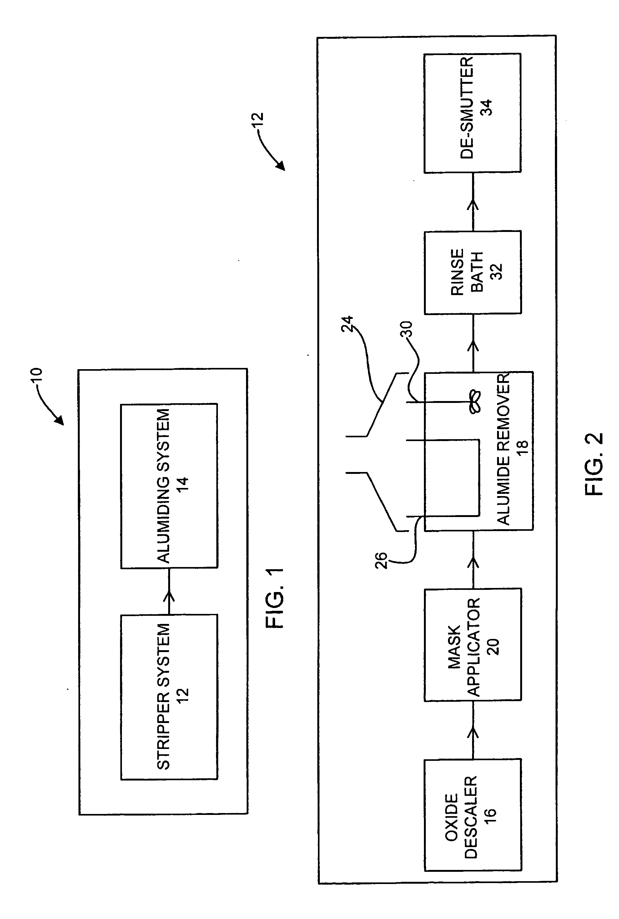
[0047] Referring now to the drawings in general and FIG. 1 in particular, it will be understood that the illustrations are for the purpose of describing a preferred embodiment of the invention and are not intended to limit the invention thereto. As best seen in FIG. 1, an airfoil refurbishment system, generally designated 10, is shown constructed according to the present invention. The airfoil refurbishment system 10 includes two major sub-assemblies, a stripper system 12 and an aluminiding system 14. As such, an airfoil refurbishment system 10 may be contained within a single building or a single facility.

[0048] One advantage of such an


PUM

PropertyMeasurementUnit
Areaaaaaaaaaaa

Abstract

An airfoil refurbishment system is disclosed. The airfoil refurbishment system includes an environmentally safe stripper system and an aluminiding system. The environmentally safe stripper system includes a transportable environmentally safe compound that is capable of partially removing an aluminide coating from an airfoil. The aluminiding system is capable of restoring the aluminide coating to the airfoil.

Description


Claims


Application Information

Patent Timeline
Owner LAGRAFF JOHN ROBERT
Why Eureka
Try Eureka