Loading implement

Inactive Publication Date: 2007-03-15
DEERE & CO
View PDF3 Cites 10 Cited by
  • Summary
  • Abstract
  • Description
  • Claims
  • Application Information

AI Technical Summary

Benefits of technology

[0011] In a further embodiment the devices can include pressure sensors that are arranged at one or more hydraulic or pneumatic actuators preferably hydraulic cylinders that are preferably located between a frame and the axles of the loading implement. Such hydraulic cylinders can be applied in order to maintain or change an adjustable position of the frame with respect to a list or heeling relative to the ground under the loading implement or with respect to the axles. In addition these hydraulic cylinders can also be used to change the spring support of the axles

Problems solved by technology

The disadvantage here is that when the pressure of the hydraulic cylinder is reduced with an active spring support, this cannot be recognized by the sprin

Method used


Image

  • Loading implement
  • Loading implement
  • Loading implement

Examples


Embodiment Construction

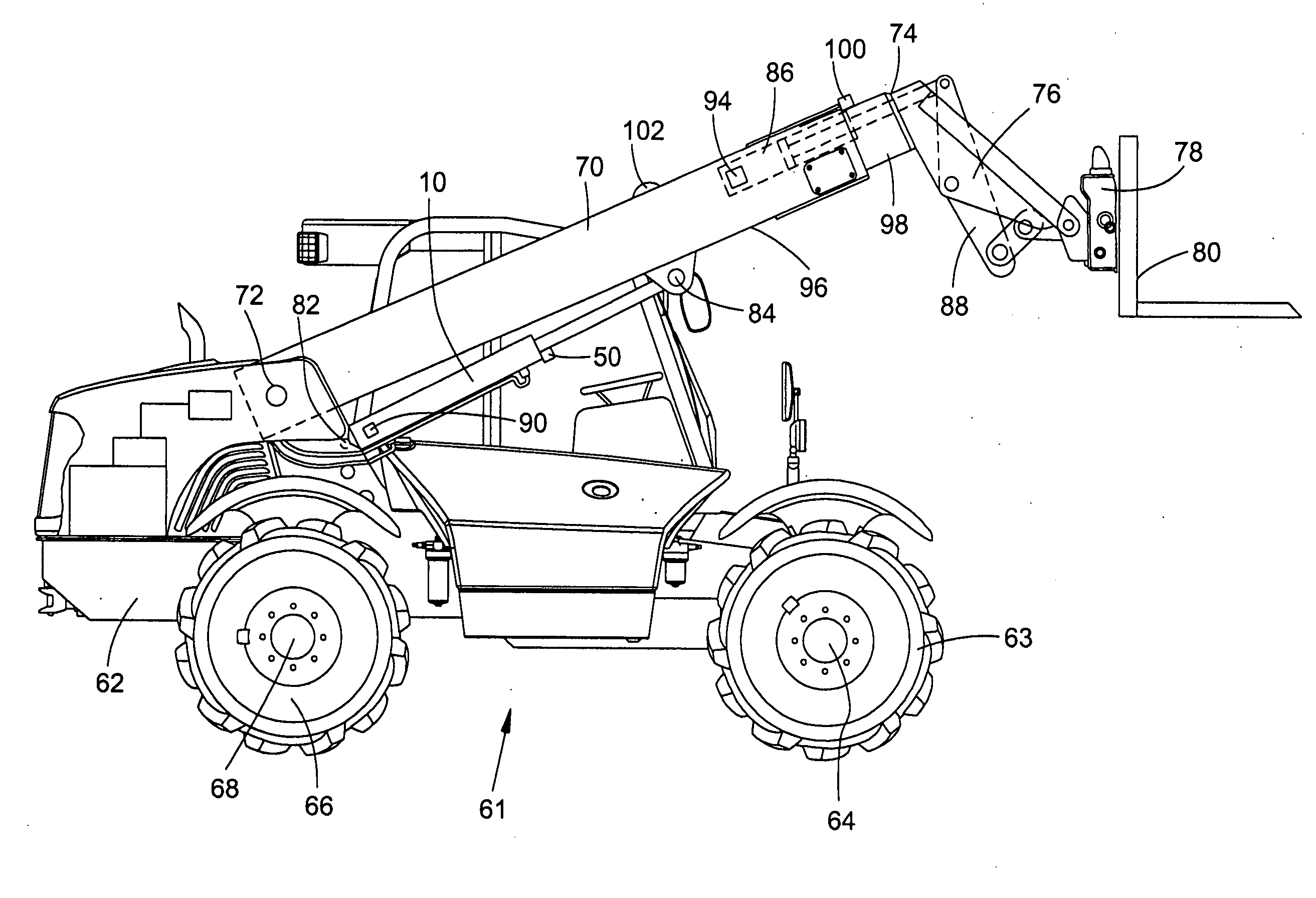
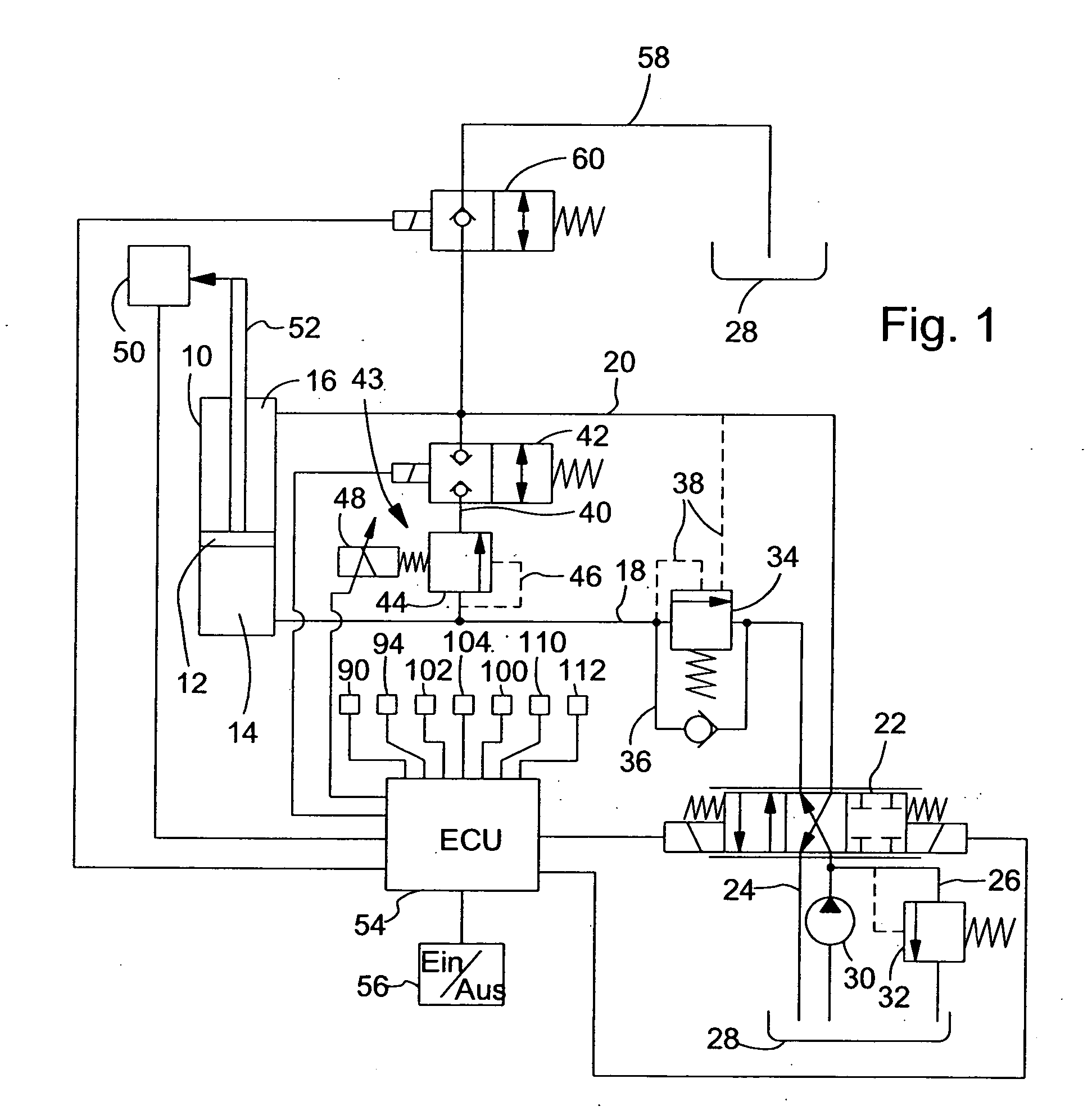
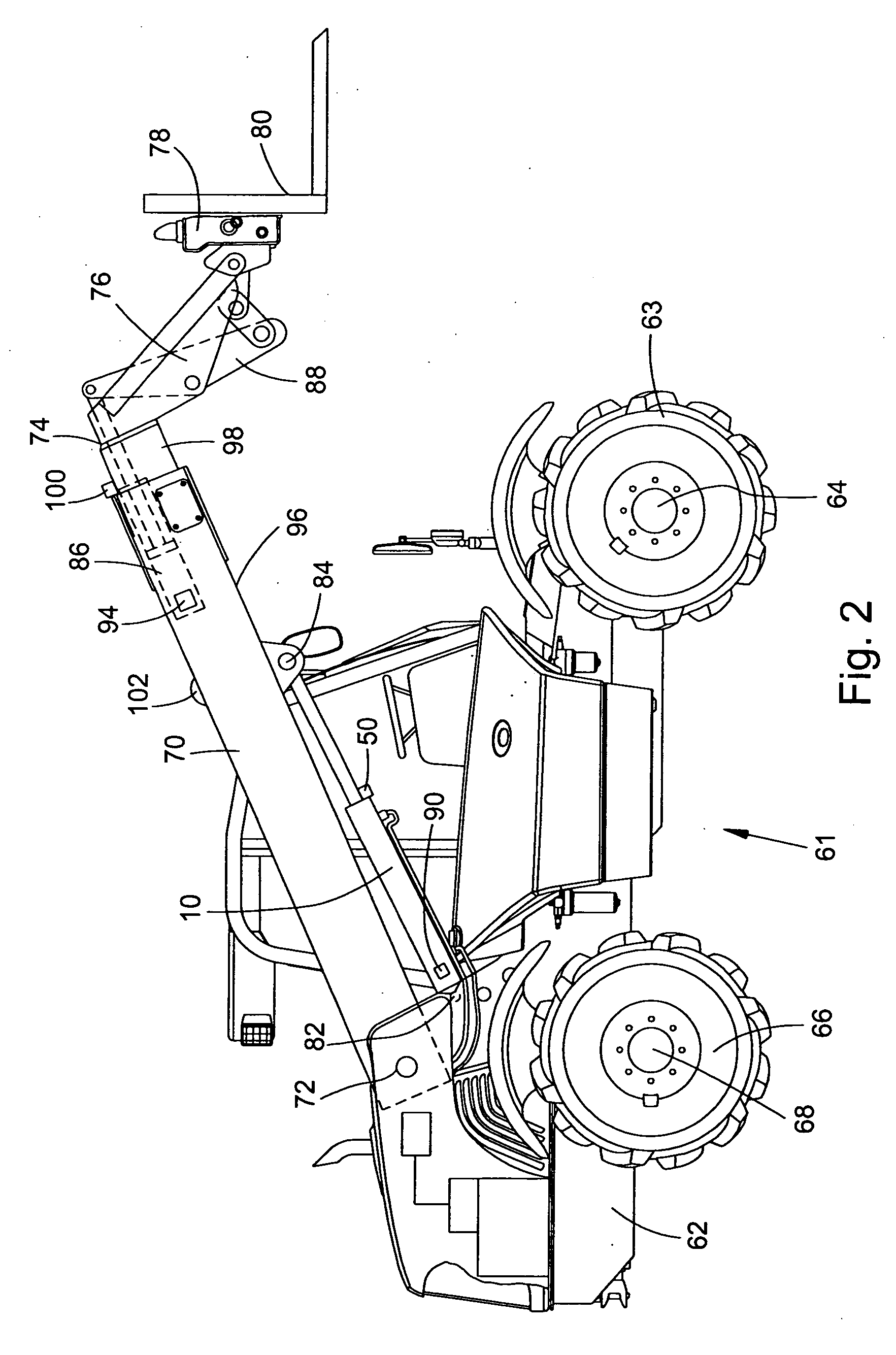
[0018]FIG. 1 shows a hydraulic cylinder 10 with a hydraulic piston 12 that is used for the lifting and lowering of a boom 70 of a loading implement 61 (both shown in FIG. 2).

[0019] The hydraulic cylinder 10 is provided with a lifting side chamber 14 and a lowering side chamber 16. The lifting side chamber 14 is connected with an electrically controllable control implement 22 over a lifting side hydraulic line 18 and the lowering side chamber 16 is connected with the control implement 22 over a lowering side hydraulic line 20.

[0020] The control implement 22 is connected with a hydraulic fluid tank 28 over a drain line 24 and over a pressure limiting line 26. A hydraulic fluid pump 30 conveys hydraulic fluid into each of the hydraulic lines 18, 20 over the control implement 22.

[0021] The control implement 22 can be switched into three positions, a closed position in which no hydraulic fluid flows into the hydraulic lines 18, 20, in a lifting position in which hydraulic fluid is suppli


PUM


Abstract

A loading implement is provided with a hydraulic arrangement for the spring support of a boom. The hydraulic arrangement is provided with at least one hydraulic conveying device, a hydraulic fluid tank, a first hydraulic cylinder and a control implement for the lifting and lowering of the boom, as well as a controllable pressure limiting arrangement that is arranged and configured in such a way that excursion movements of the first hydraulic cylinder can be equalized. The equalization is performed by a control unit for the control of the pressure limiting arrangement. In order to correct the spring support performance of the hydraulic arrangement when a change in the loading of the hydraulic cylinder occurs, devices are provided with which a change in the loading condition of the boom can be detected as well as a signal reproducing the loading condition can be generated and that the signal reproducing the loading condition can be processed by the control unit.

Description


Claims


Application Information

Patent Timeline
Owner DEERE & CO
Why Eureka
Try Eureka