Rotating stand (carousel) bottle and tube holder

Inactive Publication Date: 2007-03-22
DONNELLAN JENNIFER
View PDF11 Cites 24 Cited by
  • Summary
  • Abstract
  • Description
  • Claims
  • Application Information

AI Technical Summary

Benefits of technology

[0023] In its simplest form, the present invention is a holder or display for storing, displaying, and conveniently using Consumables. Such Consumables may include tubes or bottles of various shades of hair colors used by a beautician, or offered for sale at a retail counter. The holder or display comprises a rotating stand (referred to generally herein as the “Carousel”) comprising at least two disks into which holes are formed. Into the holes of the disks, consumables are placed for display, and for easy storage and access. The Carousel allows a technician or a purchaser to easily select the correct consumable from among many similar consumables differing in one or more characteristics, as such technician or purchaser may easily view such products, and s

Problems solved by technology

Oftentimes, Consumables are not of shapes suitable to allow stacking.
Stacking, of course, has significant disadvantages, including instability in the stack and consequent disarray, insufficient view of package names or colors for convenient selection and replacement, and similar disadvantages.
And oftentimes the outer containers for such consumables serve no useful purpose other than to provide an imperfect means to stack Consumables, and such containers are therefore soon discarded.
While holders of various kinds exist in pri

Method used


Image

  • Rotating stand (carousel) bottle and tube holder
  • Rotating stand (carousel) bottle and tube holder
  • Rotating stand (carousel) bottle and tube holder

Examples


Example

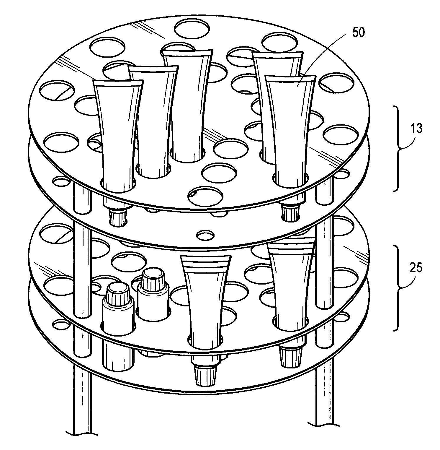
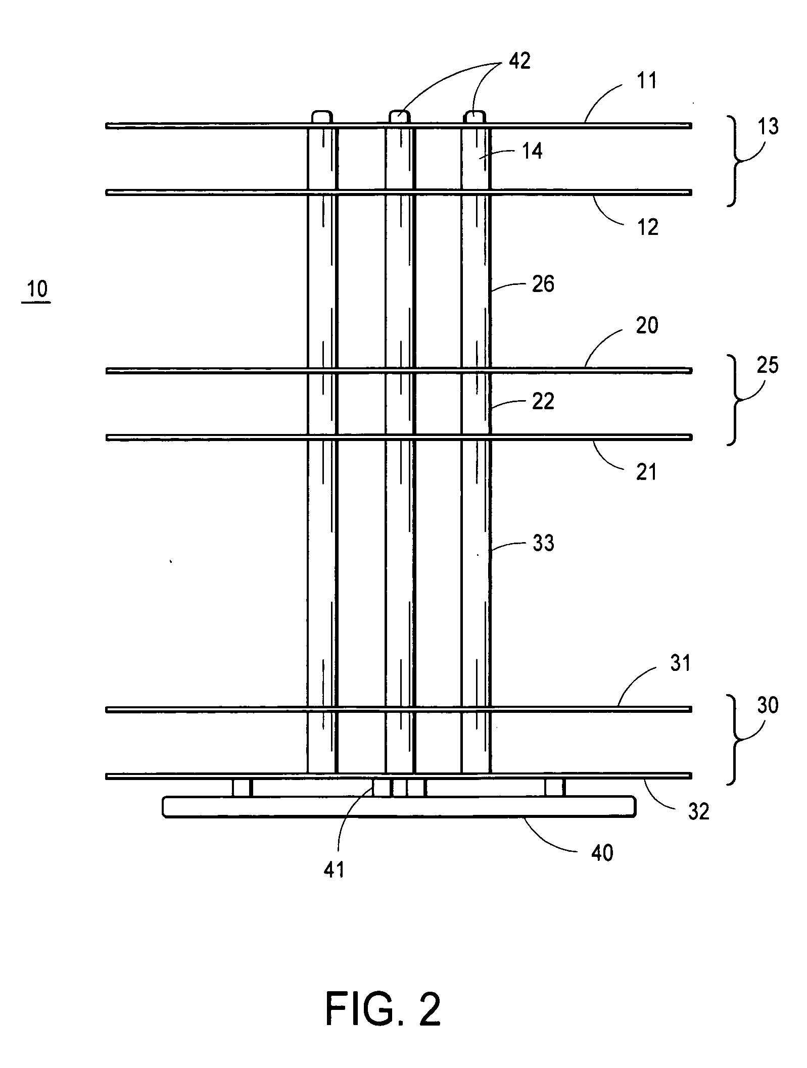
[0064] Referring initially to FIG. 1, a first preferred embodiment of the Carousel of the present invention is shown in perspective view, viewed from above the level of its topmost Disk. In FIG. 1, the Carousel of the present invention 10 has a substantially circular and flat upper Disk 11 ganged with a similar substantially circular and flat lower Disk 12 in a topmost Disk tier, or Pair 13 of Disks. In one preferred embodiment, Disk 11 and Disk 12 are approximately fourteen and one-half inches in diameter, however a wide variety of Disk diameters may be used, depending on the size of the container or tube containing the Consumable at hand (not shown), so long as each Disk is approximately the same diameter in any single Carousel assembly. The Pair 13 are so ganged by utilizing three vertically oriented Bars 14 of substantially equal length. Bars 14 and Disks 11 and 12 are preferably composed of metal, preferably machined from steel or aluminum, however other materials are possible, an


PUM


Abstract

A holder for displaying and conveniently using consumables is disclosed, in which a two or more disks having corresponding, but differently sized, holes, arranged in rows, are ganged into a pair of disks, thereby allowing users to place bottles and tubes containing consumables into such holes for easy storage and access. The pair of disks is provided with rotational means, additional pairs of disks may be added in a modular fashion to increase storage capacity, and the rows of holes may be non-radially arranged, or even spirally arranged, to increase view and access to bottles and tubes.

Description


Claims


Application Information

Patent Timeline
Owner DONNELLAN JENNIFER
Why Eureka
Try Eureka