Dissipative pick and place tools for light wire and LED displays

Inactive Publication Date: 2007-04-19
REIBER STEVEN F
View PDF98 Cites 12 Cited by
  • Summary
  • Abstract
  • Description
  • Claims
  • Application Information

AI Technical Summary

Benefits of technology

[0010] An exemplary embodiment of the present invention discloses a method for placement of LEDs. Through this exemplary method, holes are cut in a light wire strip for the acceptance of an LED device. An LED device is placed in each of these holes and a current wire is embedded in the light strip. The current

Problems solved by technology

Despite being small, these bulbs occupied a great deal of space.
Further, light bulbs were often too fragile for some settings (e.g., airplanes and cruise ships) and/or methods of manufacture.
Notwithstanding the increased manageability and durability offered by the LED, other difficulties still exist with respect to light rope and light wire manufacture.
These chip carriers are generally very expensive and are also difficult to work with not only because they are large

Method used


Image

  • Dissipative pick and place tools for light wire and LED displays
  • Dissipative pick and place tools for light wire and LED displays
  • Dissipative pick and place tools for light wire and LED displays

Examples


Embodiment Construction

[0033] Various embodiments of the present invention allow for an LED to be picked up from a wafer and placed on a carrier with a pick-and-place tool or machine. The part of the tool that comes in contact with the LED is, in an embodiment, made with a conductive or insulative material that conducts electricity at a rate sufficient to prevent charge buildup but not at so high a rate as to overload the LED.

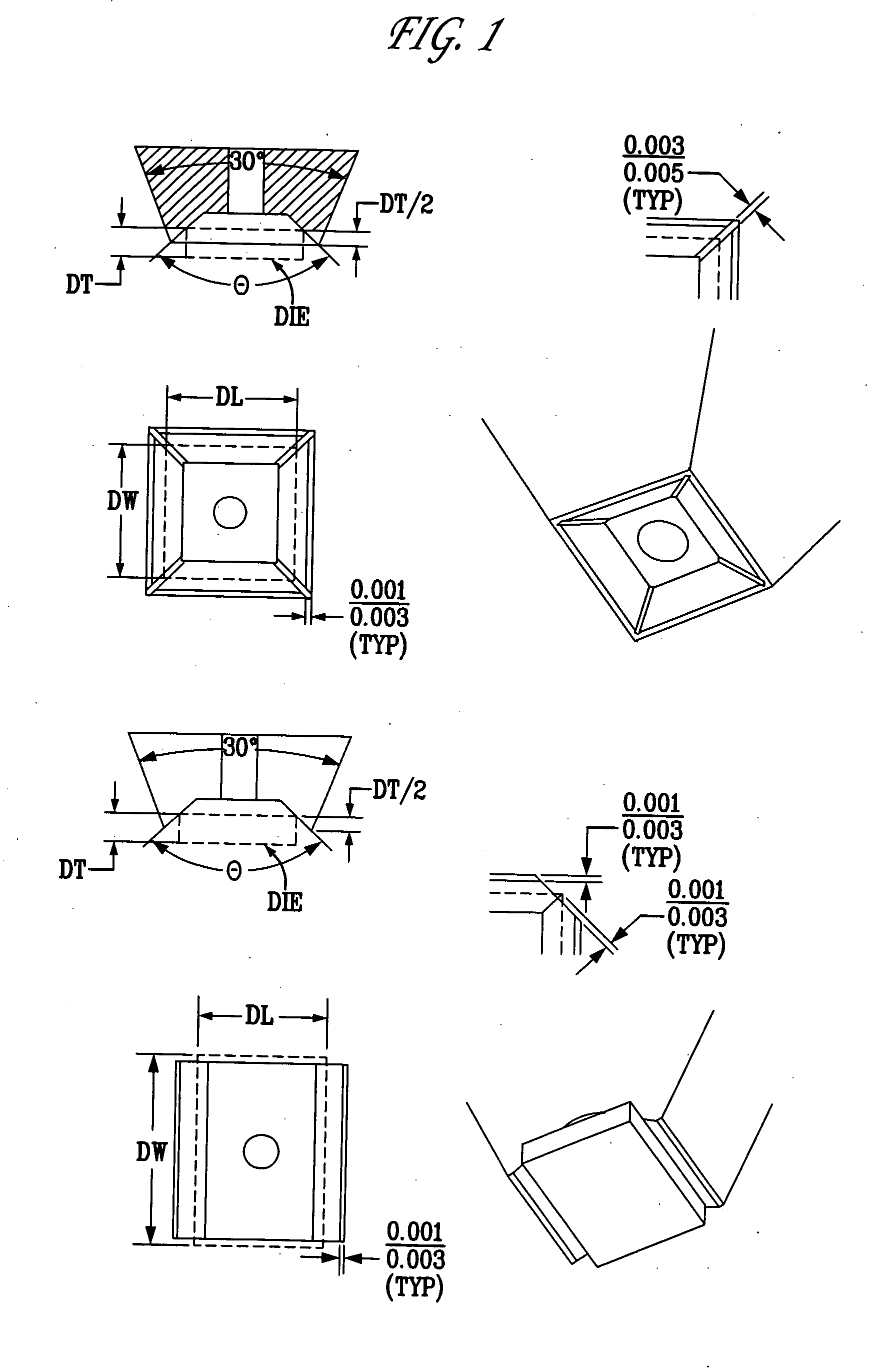
[0034]FIG. 1 illustrates a series of exemplary die collets, which may be used in various embodiments of the present invention with respect to conducting electricity at a rate sufficient to prevent charge buildup and also at a rate that prevents an overload of a device in contact or physical proximity of the die collets. Die collets may be used to attach, for example, a die to a substrate. The inside of die collets, in exemplary embodiments, may have slants sides (for example, 90 degrees) but may be modified to various slant configurations depending upon the needs of the particular tool


PUM


Abstract

The present invention provides for placement of an LED device on a carrier through the use of a pick-and-place tool. The tool conducts electricity at a rate sufficient to prevent charge buildup but not at so high a rate as to overload the LED being placed.

Description


Claims


Application Information

Patent Timeline
Owner REIBER STEVEN F
Why Eureka
Try Eureka