Methods and apparatus for assembling gas turbine engine stator assemblies

a technology for gas turbine engines and stator assemblies, which is applied in the field of gas turbine engines, can solve the problems of undetectable slippage of known spline seals, damage to other engine components, and limit the useful life of the turbine nozzle, so as to facilitate reducing leakage, facilitate retaining, and facilitate the effect of reducing leakag

Active Publication Date: 2007-06-21
GENERAL ELECTRIC CO
View PDF13 Cites 13 Cited by
  • Summary
  • Abstract
  • Description
  • Claims
  • Application Information

AI Technical Summary

Benefits of technology

This patented describes methods used during manufacturing gas turbines engines by attaching two different types of gears together without any leaks or other issues like improving efficiency. These techniques include fitting these components tightly together while maintaining their proper alignment, creating spaces where certain parts can be easily inserted when needed, adding extra features like splashes on surfaces inside the space, allowing some small cracks to form if they are too big. Additionally, it provides various ways to prevent damage caused by external factors (such as vibrations) which could cause them to break loose. Overall, this technology helps improve performance and durability of gas turbojet engines over time.

Problems solved by technology

The technical problem addressed in this patented text is how to assemble gas turbojet engines without damaging nearby parts caused due to leakage of lubricating oil during maintenance procedures while also ensuring proper functioning of these systems.

Method used


Image

  • Methods and apparatus for assembling gas turbine engine stator assemblies
  • Methods and apparatus for assembling gas turbine engine stator assemblies
  • Methods and apparatus for assembling gas turbine engine stator assemblies

Examples


Embodiment Construction

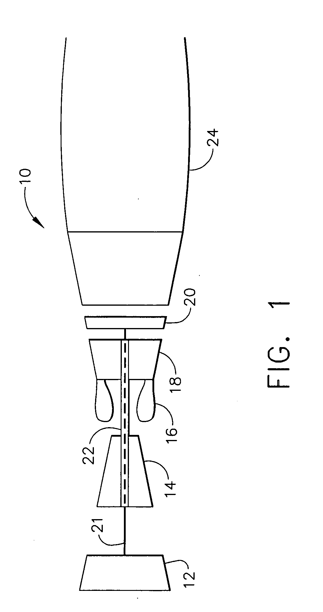
[0016]FIG. 1 is a schematic illustration of an exemplary gas turbine engine 10 including a low pressure compressor 12, a high pressure compressor 14, and a combustor 16. Engine 10 also includes a high pressure turbine 18 and a low pressure turbine 20. Compressor 12 and turbine 20 are coupled by a first shaft 21, and compressor 14 and turbine 18 are coupled by a second shaft 22. In one embodiment, gas turbine engine 10 is an LM2500 engine commercially available from General Electric Aircraft Engines, Cincinnati, Ohio. In another embodiment, gas turbine engine 10 is a CFM engine commercially available from General Electric Aircraft Engines, Cincinnati, Ohio.

[0017] In operation, air flows through low pressure compressor 12 supplying compressed air from low pressure compressor 12 to high pressure compressor 14. The highly compressed air is delivered to combustor 16. Airflow from combustor 16 is channeled through a turbine nozzle (not shown in FIG. 1) to drive turbines 18 and 20, prior to


PUM


Abstract

A method for assembling a gas turbine engine is provided. The method comprises coupling a first turbine nozzle within the engine, coupling a second turbine nozzle circumferentially adjacent the first turbine nozzle such that a gap is defined between the first and second turbine nozzles and providing at least one spline seal including a substantially planar body. The method also comprises forming at least one catch to extend outward from the body portion of the at least one spline seal, and inserting the at least one spline seal into a slot defined in at least one of the first and second turbine nozzles to facilitate reducing leakage through said gap, such that a portion of the at least one spline seal is received within a recess defined within the turbine nozzle slot to facilitate retaining the at least one spline seal within the turbine nozzle slot.

Description


Claims


Application Information

Patent Timeline
Owner GENERAL ELECTRIC CO
Why Eureka
Try Eureka