Management system, management program-recorded recording medium, and management method
a management system and program recording technology, applied in program control, sustainable buildings, instruments, etc., can solve the problems of power consumption without a decrease in serviceability, computer failures, etc., and achieve the effect of maintaining the total operation amount of the computer and saving energy for cooling
- Summary
- Abstract
- Description
- Claims
- Application Information
AI Technical Summary
Benefits of technology
Problems solved by technology
Method used
Image

Examples
embodiment 1
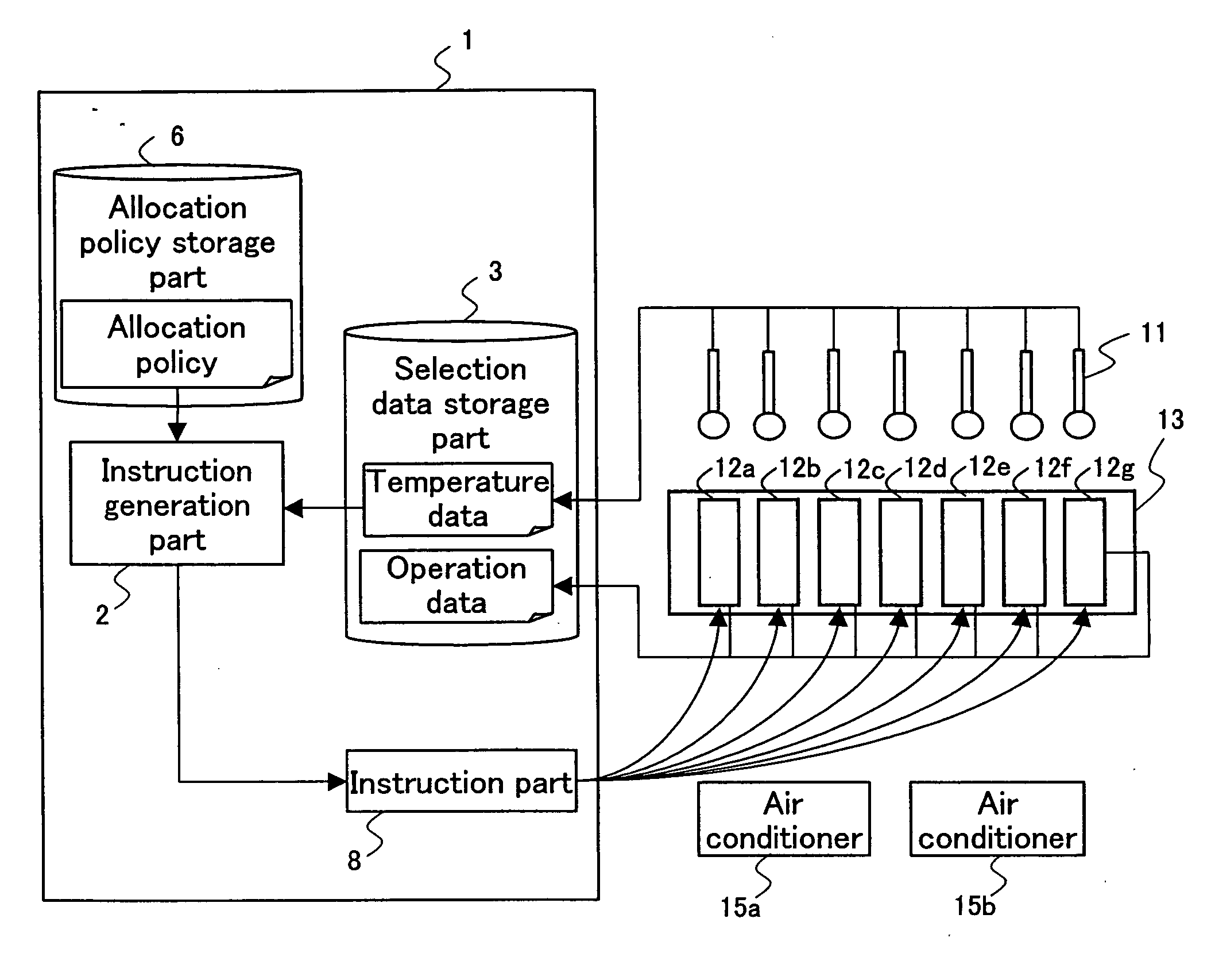
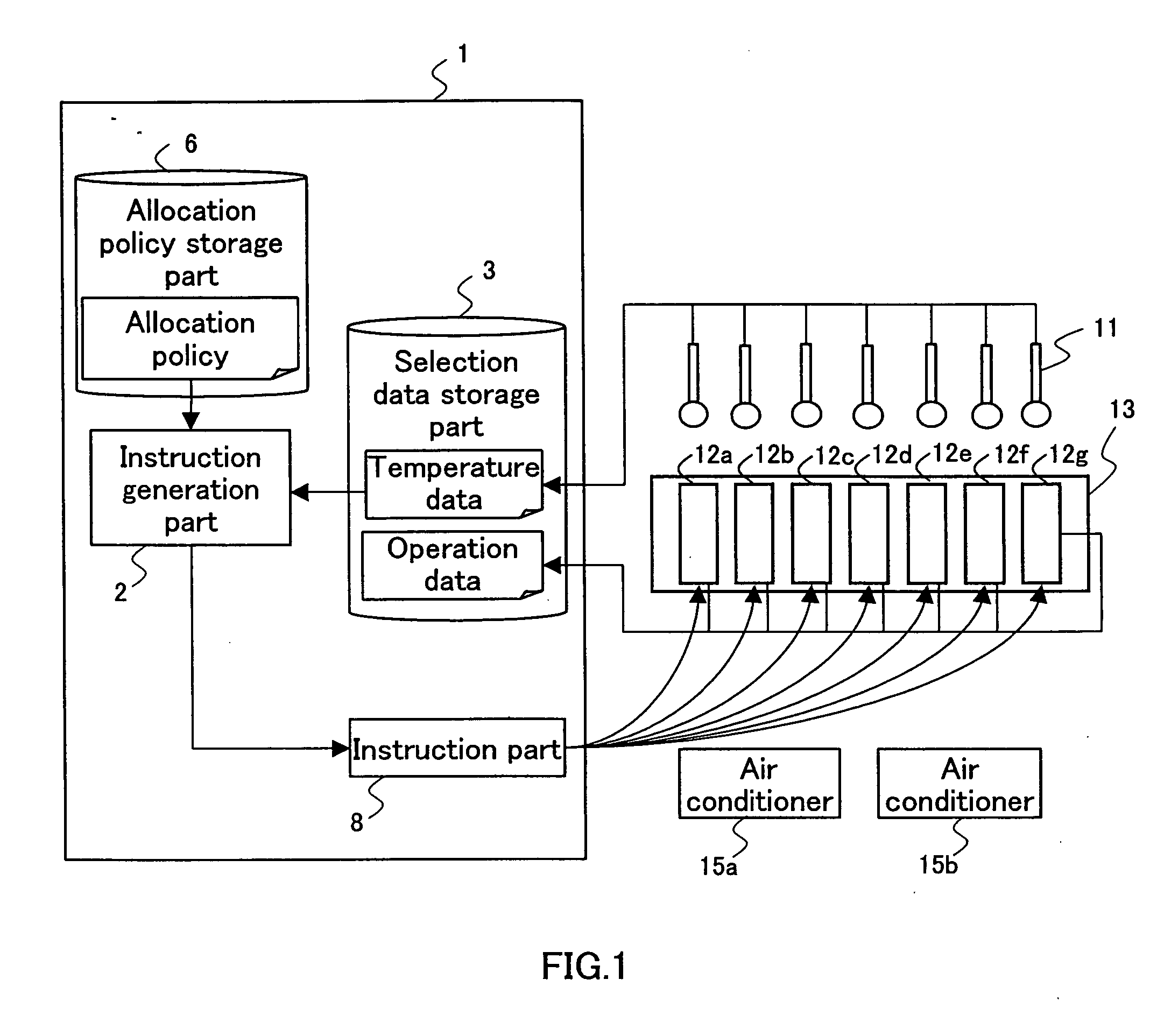
[0046] An IDC shown in FIG. 1 includes a management system 1, a rack 13 containing blade servers 12a to 12g, temperature sensors 11, and air conditioners 15a and 15b.
[0047] The management system 1 includes a selection data storage part 3 for storing data regarding allocation destination selection, an allocation policy storage part 6, an instruction generation part 2, and an instruction part 8. The management system 1 is connected with a plurality of the blade servers 12a to 12g contained in the rack 13. In the vicinities of the rack 13, air conditioners 15a and 15b are disposed that control the temperature of space Where the rack 13 is disposed. The air conditioner 15a shown in FIG. 1 has a function for controlling the temperature in the vicinity of the blade servers 12a to 12c, while the air conditioner 15b has a function of controlling the temperature in the vicinity of the blade servers 12d to 12g.
[0048] It should be noted that in the example shown in FIG. 1, the management system
embodiment 2
[0125] Embodiment 1 is based on the premise that one OS is installed in one blade server, but there is software, such as Xen, VMWare, etc., that activates a plurality of OSes in one blade server, thereby allowing the physically single blade server to be used as a plurality of logical machines. Therefore, in some cases, a virtualization technology with which one blade server is treated as a plurality of virtual machines is applied. There is also a virtualization technology with which a plurality of blade servers are treated as a single virtual machine.
[0126] Therefore, the description of the present embodiment describes a case where software allocated to a plurality of blade servers virtually treats the plurality of blade servers as one machine, and a case where software allocated to one blade server treats the blade server as a plurality of virtual machines.
[0127] First, a case where software for performing processing with use of the blade servers 12a to 12g shown in FIG. 1 treats a
embodiment 3
[0141] Another embodiment of the present invention is described below with reference to the drawings. The configurations having the same functions as the configurations of Embodiment 1 described above are designated with the same reference numerals and descriptions of the same are omitted.
[0142]FIG. 15 is a functional block diagram illustrating a configuration of an IDC including a management system 10 according to the present embodiment. The management system 10 shown in FIG. 15 has a configuration obtained by modifying the management system 1 (FIG. 1) according to Embodiment 1 by further including a cost data storage part 7 therein. An instruction generation part 2a generates an instruction based on data stored in the cost data storage part 7 also, in addition to temperature data, operation data, and an allocation policy. The instruction generation part 2a also generates instructions directed to the air conditioners 15a and 15b. An instruction part 8a transmits the instructions for
PUM
 Abstract
Description
Claims
Application Information
 - R&D Engineer
- R&D Manager
- IP Professional
- Industry Leading Data Capabilities
- Powerful AI technology
- Patent DNA Extraction
Browse by: Latest US Patents, China's latest patents, Technical Efficacy Thesaurus, Application Domain, Technology Topic.
© 2024 PatSnap. All rights reserved.Legal|Privacy policy|Modern Slavery Act Transparency Statement|Sitemap