Vertical magnetic recording medium
a vertical magnetic recording and magnetic recording technology, applied in the field of magnetic recording mediums, can solve the problems of increasing the recording magnetic file, limited effect, so-called thermal fluctuation, etc., and achieve the effect of improving the saturation magnetization ms of the vertical magnetic recording layer and improving the reproduction output of the vertical magnetic recording medium
- Summary
- Abstract
- Description
- Claims
- Application Information
AI Technical Summary
Benefits of technology
Problems solved by technology
Method used
Image

Examples
first embodiment
A First Embodiment
[0024] The vertical magnetic recording medium according to a first embodiment of the present invention will be explained with reference to FIGS. 1 to 6.
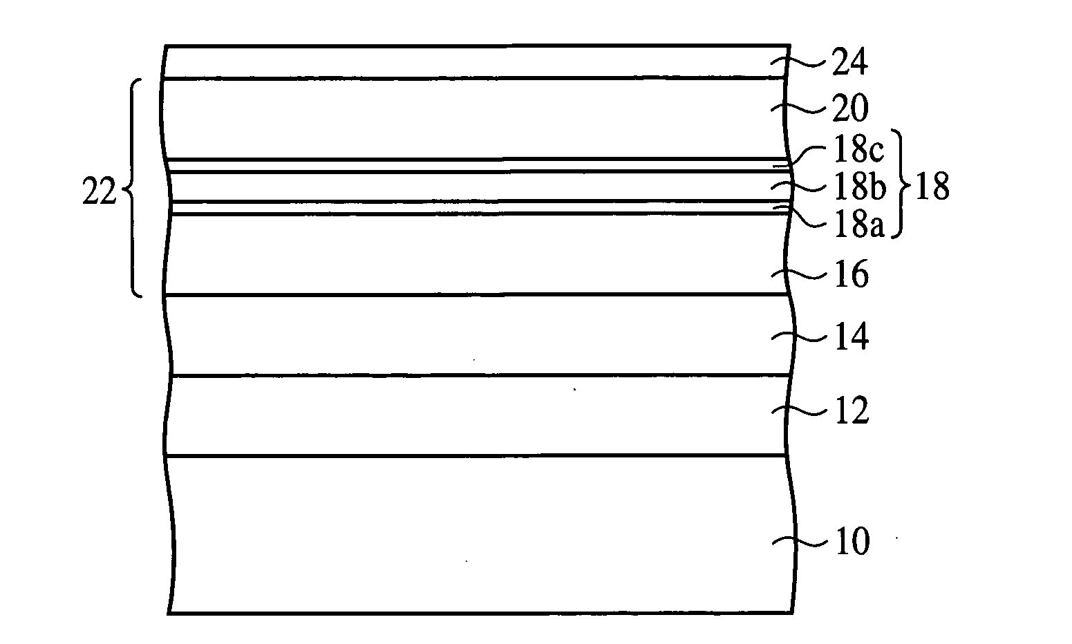
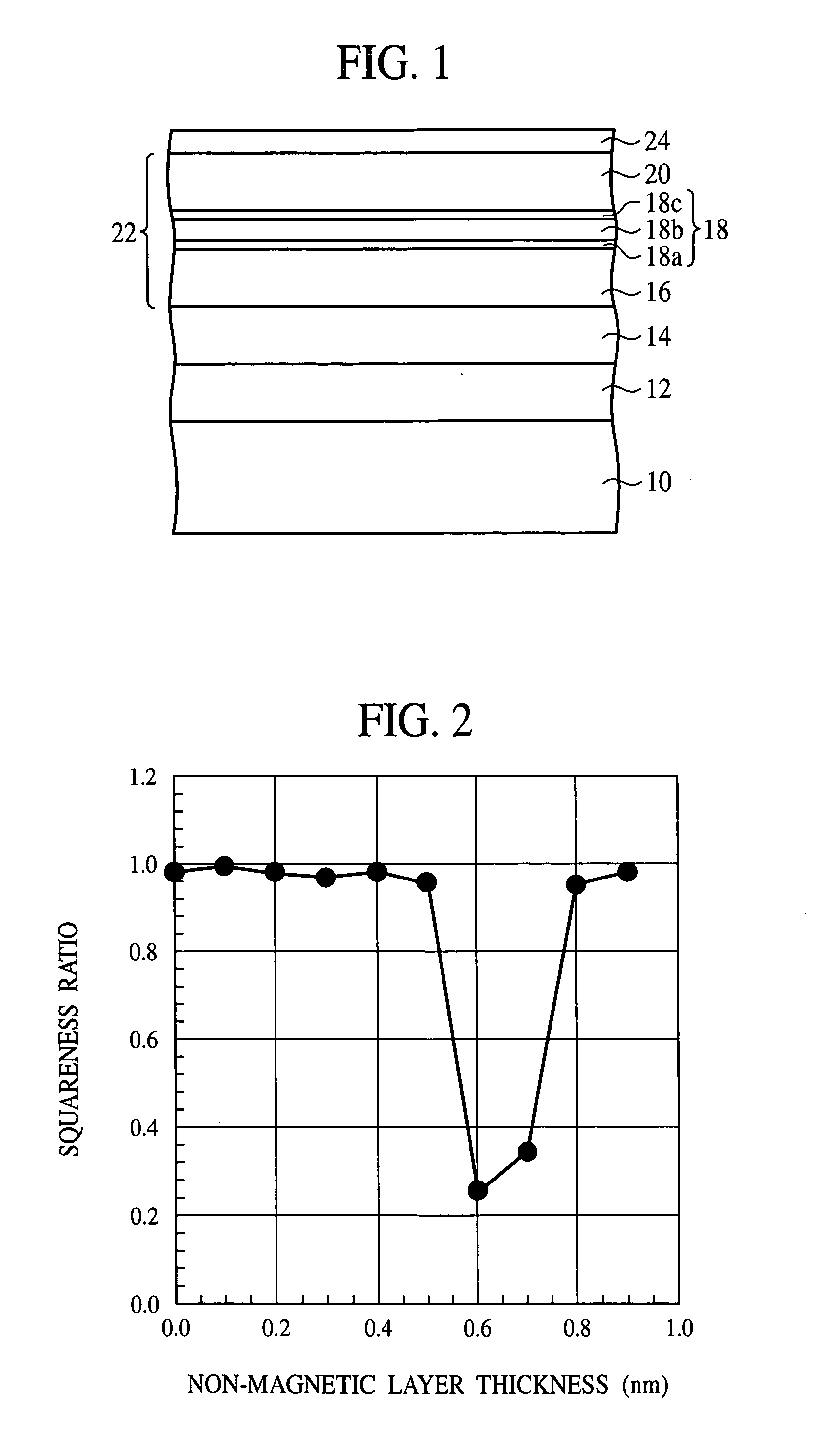
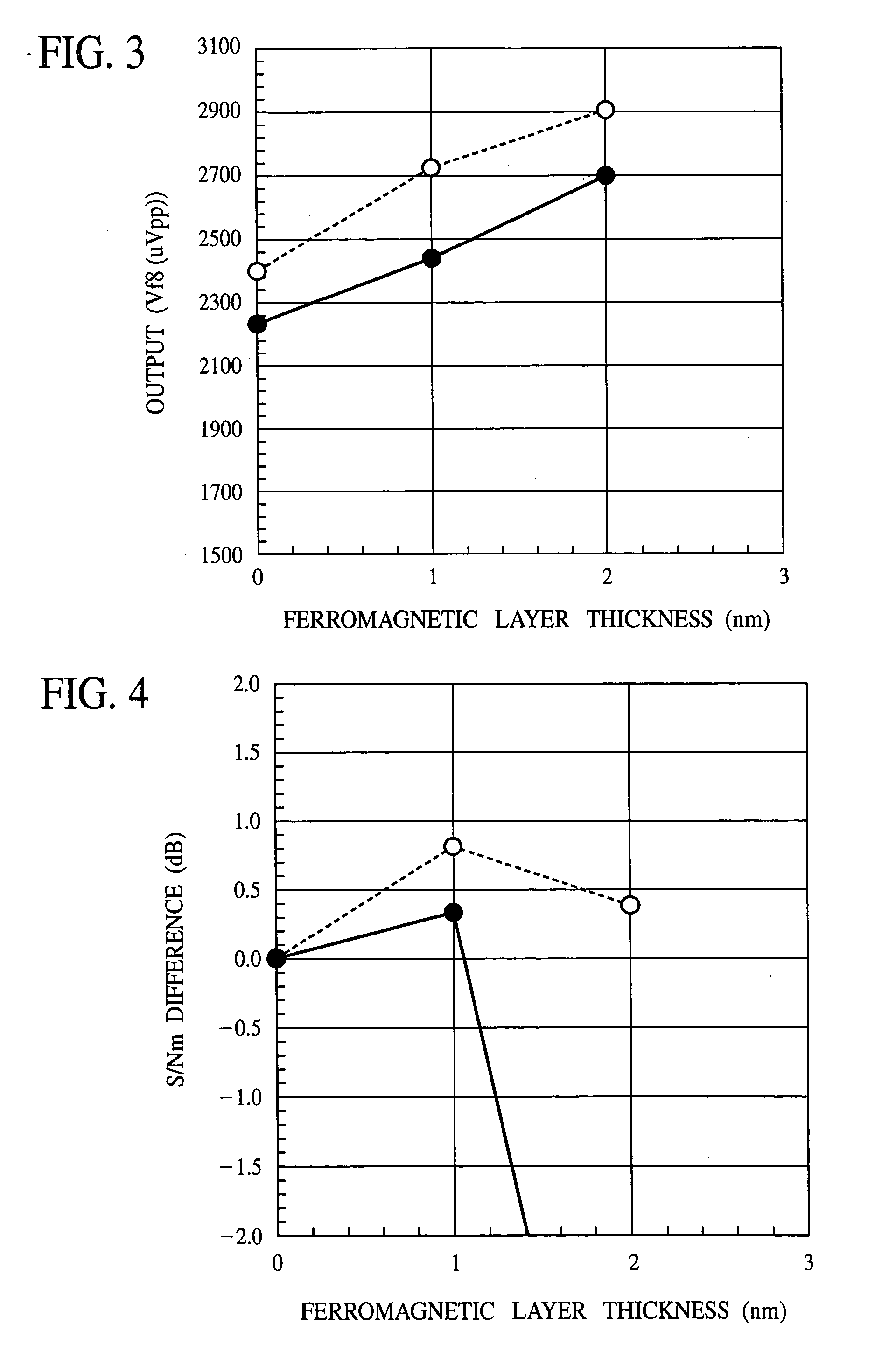
[0025]FIG. 1 shows a diagrammatic sectional view of a structure of the vertical magnetic recording medium according to the present embodiment. FIG. 2 is a graph showing the non-magnetic layer thickness dependency of the squareness ratio. FIGS. 3 and 6 are graphs showing the ferromagnetic layer thickness dependency of output. FIG. 4 is a graph showing the ferromagnetic layer thickness dependency of the S / N ratio. FIG. 5 is a graph showing changes of the coercive force for angles of the measuring direction of the magnetic characteristics.
[0026] First, the structure of the vertical magnetic recording medium according to the present embodiment will be explained with reference to FIG. 1.
[0027] A backing layer 12 of a soft magnetic material is formed on a glass substrate 10. On the backing layer 12, an intermediate laye
second embodiment
A Second Embodiment
[0062] The vertical magnetic recording medium according to a second embodiment of the present invention will be explained with reference to FIGS. 7A to 8. The same members of the present embodiment as those of the vertical magnetic recording medium according to the first embodiment shown in FIG. 1 are represented by the same reference numbers not to repeat or to simplify their explanation.
[0063]FIGS. 7A and 7B are diagrammatic sectional views of the vertical magnetic recording medium according to the present embodiment, which showns a structure thereof. FIG. 8 is a graph of the ferromagnetic layer film thickness dependency of the S / N ratio.
[0064] First, the structure of the vertical magnetic recording medium according to the present embodiment will be explained with reference to FIGS. 7A and 7B. FIG. 7A is a sectional view of the vertical magnetic recording medium according to the present embodiment, which shows the general structure. FIG. 7B is an enlarged secti
third embodiment
A Third Embodiment
[0088] The magnetic recording device according to a third embodiment of the present invention will be explained with reference to FIG. 9.
[0089]FIG. 9 is a diagrammatic view of the magnetic recording device according to the present embodiment, which shows a structure thereof.
[0090] In the present embodiment, the magnetic recording device using the vertical magnetic recording medium according to the first or the second embodiment will be explained.
[0091] The magnetic recording device 30 according to the present embodiment includes a box body 32 defining, e.g., a lengthy cuboid interior space. The housing space accommodates one or more magnetic discs 34 as the recording media. The magnetic disc 34 is the vertical magnetic recording medium according to the first embodiment shown in FIG. 1 or the vertical magnetic recording medium according to the second embodiment shown in FIGS. 7A and 7B. The magnetic disc 34 is mounted on the rotary shaft of a spindle motor 36. The s
PUM
 Abstract
Description
Claims
Application Information
 - R&D Engineer
- R&D Manager
- IP Professional
- Industry Leading Data Capabilities
- Powerful AI technology
- Patent DNA Extraction
Browse by: Latest US Patents, China's latest patents, Technical Efficacy Thesaurus, Application Domain, Technology Topic.
© 2024 PatSnap. All rights reserved.Legal|Privacy policy|Modern Slavery Act Transparency Statement|Sitemap