Data processing unit
a data processing unit and data technology, applied in the field of data processing units, can solve the problems of difficult for users to find out desired data from the hard disk drive, complicated operation therefor, and difficulty for users to remember the da
- Summary
- Abstract
- Description
- Claims
- Application Information
AI Technical Summary
Benefits of technology
Problems solved by technology
Method used
Image

Examples
first embodiment
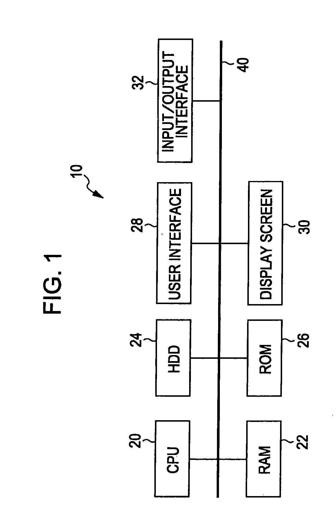
[0052]FIG. 1 a block diagram of an example of the internal structure of an image processing unit according to a first embodiment. Examples of the image processing unit, denoted by reference numeral 10, include information processing units of notebook or desktop personal computers, mobile phones in which image data can be stored, printers having a display screen, and photo viewers.
[0053]As shown in FIG. 1, the image processing unit 10 according to the first embodiment includes, for example, a central processing unit (CPU) 20, a random access memory (RAM) 22, a hard disk drive 24, a read only memory (ROM) 26, a user interface 28, a display screen 30, and an input / output interface 32, which are mutually connected via an internal bus 40.
[0054]The hard disk drive 24 is an example of a high-storage image storage section in which high volumes of image data is stored. Here, the image data is assumed to be still-image data; it may include moving-image data.
[0055]The user interface 28 is a dev
second embodiment
[0107]In the first embodiment, the presence and volume of the images in the image-taking-date representing section E20 are expressed by changes in the light and shade of a specific color. In contrast, in a second embodiment, the presence and volume of the images are expressed by changes in hue. The difference from the first embodiment will be described hereinbelow.
[0108]FIG. 15 shows an example of the structure of an image-distribution display area W24 according to the second embodiment. As shown in FIG. 15, also the image-taking-date representing section E20 of the second embodiment has circumferential rings C20 to C24, in which the lapse of months from January to December is expressed circumferentially and the lapse of years is expressed radially.
[0109]In this embodiment, the presence and number of the images are expressed by changes in the hue of the circumferential rings C21 to C24. For example, in the circumferential rings C21 to C24 of this embodiment, the area corresponding to t
third embodiment
[0113]In the first embodiment, the presence and volume of the images are expressed by changes in light and shade in the image-taking-date representing section E20. In contrast, in a third embodiment, the presence and volume of the images are expressed by the speed of flashing. The difference from the first embodiment will be described hereinbelow.
[0114]FIG. 16 shows an example of the structure of an image-distribution display area W24 according to the third embodiment. As shown in FIG. 16, also the image-taking-date representing section E20 of the third embodiment has circumferential rings C20 to C24, in which the lapse of months from January to December is expressed circumferentially and the lapse of years is expressed radially.
[0115]In this embodiment, the presence and number of the images are expressed by changes in the flashing speed of an image-presence representing section IN of the circumferential rings C21 to C24. For example, in the circumferential rings C21 to C24 of this emb
PUM
 Abstract
Description
Claims
Application Information
 - R&D Engineer
- R&D Manager
- IP Professional
- Industry Leading Data Capabilities
- Powerful AI technology
- Patent DNA Extraction
Browse by: Latest US Patents, China's latest patents, Technical Efficacy Thesaurus, Application Domain, Technology Topic.
© 2024 PatSnap. All rights reserved.Legal|Privacy policy|Modern Slavery Act Transparency Statement|Sitemap