Milling insert and a milling insert tool for chip removing machining

a technology of inserts and milling tools, which is applied in the direction of milling equipment, turning tools, milling equipment, etc., can solve the problems of poor service life of tools, and cost-consuming and time-consuming process for making threads in hard materials

Inactive Publication Date: 2008-05-22
SECO TOOLS AB
View PDF22 Cites 10 Cited by
  • Summary
  • Abstract
  • Description
  • Claims
  • Application Information

AI Technical Summary

Benefits of technology

The technical purpose described in this patents relates to improving the performance or efficiency of metal material processing tools used during drilling operations while reducing costs associated therewith. This includes improvements such as improved wear resistance without requiring frequent replacements due to damage caused from use over time. Additionally, it provides an economic solution through cost savings when replacing worn parts instead of purchasing new ones.

Problems solved by technology

This patented technical problem addressed in this patents relates to reducing costs associated with manufacturing processes involving harder metals like grey cast irons due to their tendency towards crackling under harsh conditions when they were worked into them through various methods including millings. Additionally, there was an issue related to maintaining good quality surfaces while avoiding excessive wear over multiple hours' usage period.

Method used


Image

  • Milling insert and a milling insert tool for chip removing machining
  • Milling insert and a milling insert tool for chip removing machining
  • Milling insert and a milling insert tool for chip removing machining

Examples


Embodiment Construction

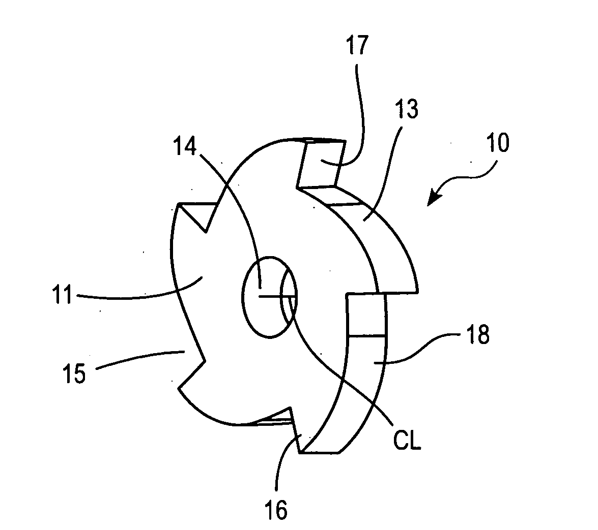
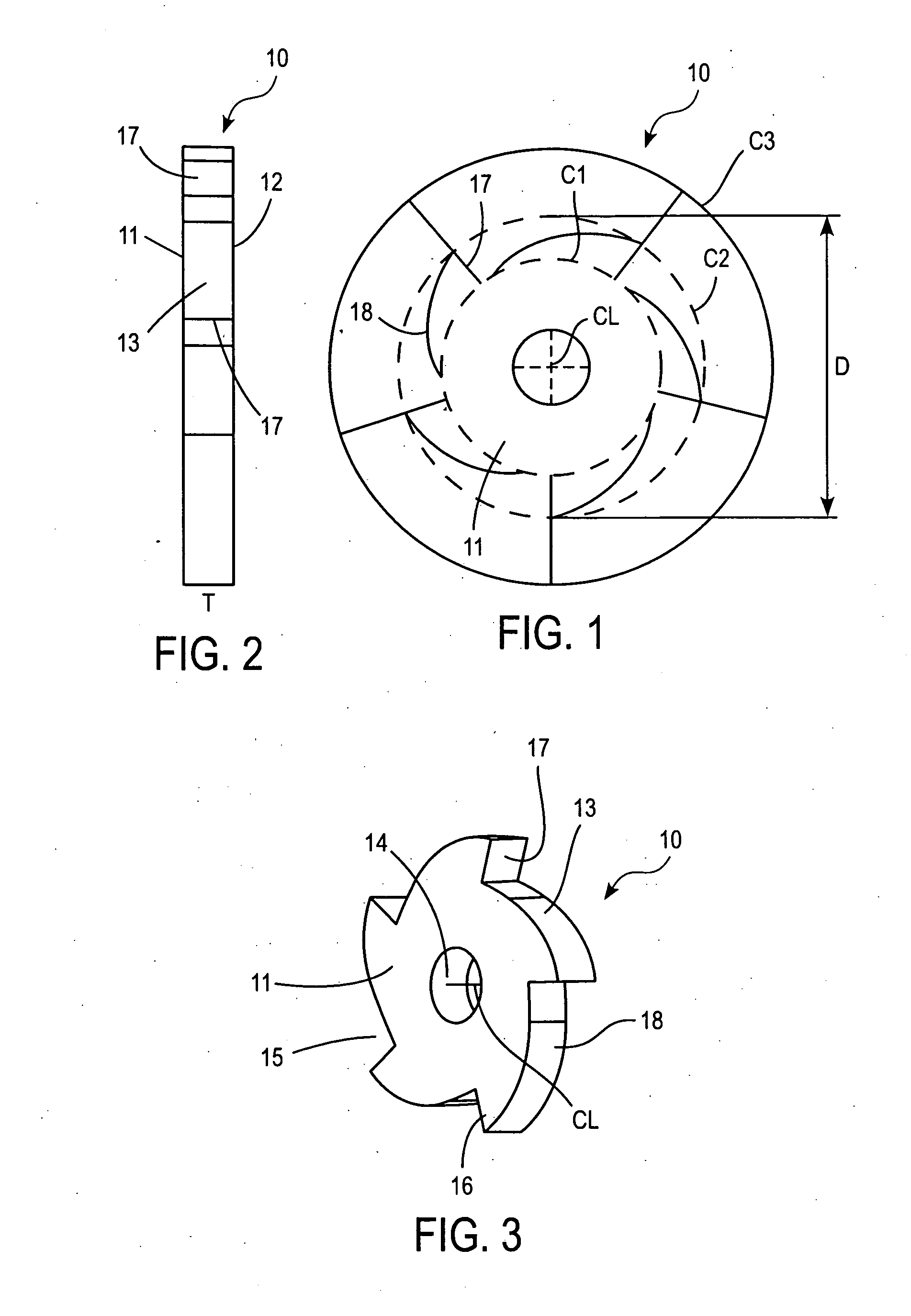
[0017]In FIGS. 1, 2 and 3, a work piece 10 is shown for a milling insert according to an embodiment of the invention. The work piece 10 consists exclusively of solid cubic boron nitride (CBN). The work piece 10 may be produced from a solid body of CBN by means of wire cutting. The work piece has the basic shape of a circular plate having a topside 11, an underside 12 as well as an edge surface 13 extending therebetween. The work piece has a thickness T, which is defined by the distance between the topside 11 and the underside 12. The thickness may be chosen in, for example, the interval of 2-5 mm. The work piece has a centrally placed, through-going hole 14. A number of recesses 15 are arranged at the periphery of the work piece, preferably produced by means of grinding. The number of recesses in the embodiment illustrated is five, but all from two to ten recesses is feasible. The recesses 15 form teeth 16 projecting from a circle C1. The circle C1 is concentric with the center axis CL


PUM

PropertyMeasurementUnit
Thicknessaaaaaaaaaa
Shapeaaaaaaaaaa

Abstract

A milling insert and a milling insert tool for chip removing machining. The milling insert includes at least two teeth. The milling insert has substantially a disc shape and includes a topside and an underside. The milling insert in its entirety is formed of cubic boron nitride.

Description


Claims


Application Information

Patent Timeline
Owner SECO TOOLS AB
Why Eureka
Try Eureka