Vehicle and control method thereof, power output apparatus and control method thereof, and driving system and control method thereof

a technology of power output apparatus and control method, which is applied in the direction of engine-driven generator propulsion, process and machine control, braking components, etc., can solve the problem of not disclosing braking control, and achieve smooth change of speed change ratio, good braking performance, and reduce variation in braking force

Active Publication Date: 2008-08-07
TOYOTA JIDOSHA KK +1
View PDF4 Cites 39 Cited by
  • Summary
  • Abstract
  • Description
  • Claims
  • Application Information

AI Technical Summary

Benefits of technology

The present invention relates to a vehicle system for improving its braking control function. It includes a drive unit that can adjust the amount of electricity input into the powertrain through different ways depending upon the desired level of braking torque delivered to each wheel or to all the wheels. By doing this, it achieves better overall efficiency and consistently maintain optimal braking behavior.

Problems solved by technology

The technical problem addressed in this patent is how to design a power output device that can adjust its power based on changes in the transmission's speed changing states without causing any discomfort or impacting performance.

Method used


Image

  • Vehicle and control method thereof, power output apparatus and control method thereof, and driving system and control method thereof
  • Vehicle and control method thereof, power output apparatus and control method thereof, and driving system and control method thereof
  • Vehicle and control method thereof, power output apparatus and control method thereof, and driving system and control method thereof

Examples


Embodiment Construction

[0030]One mode of carrying out the invention is described below as a preferred embodiment with reference to the accompanied drawings.

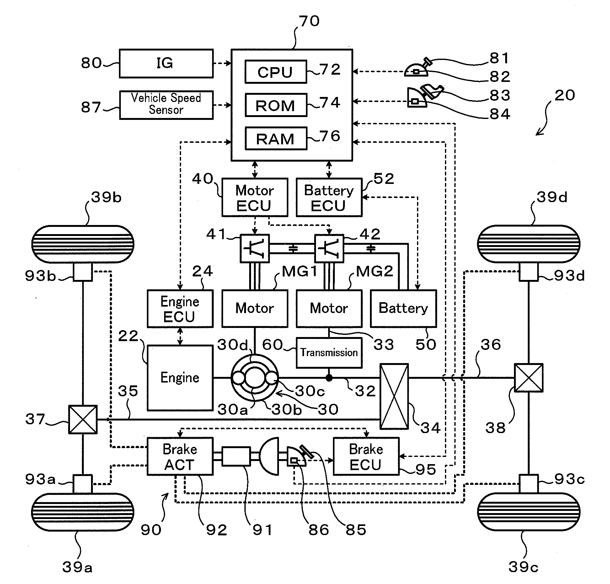
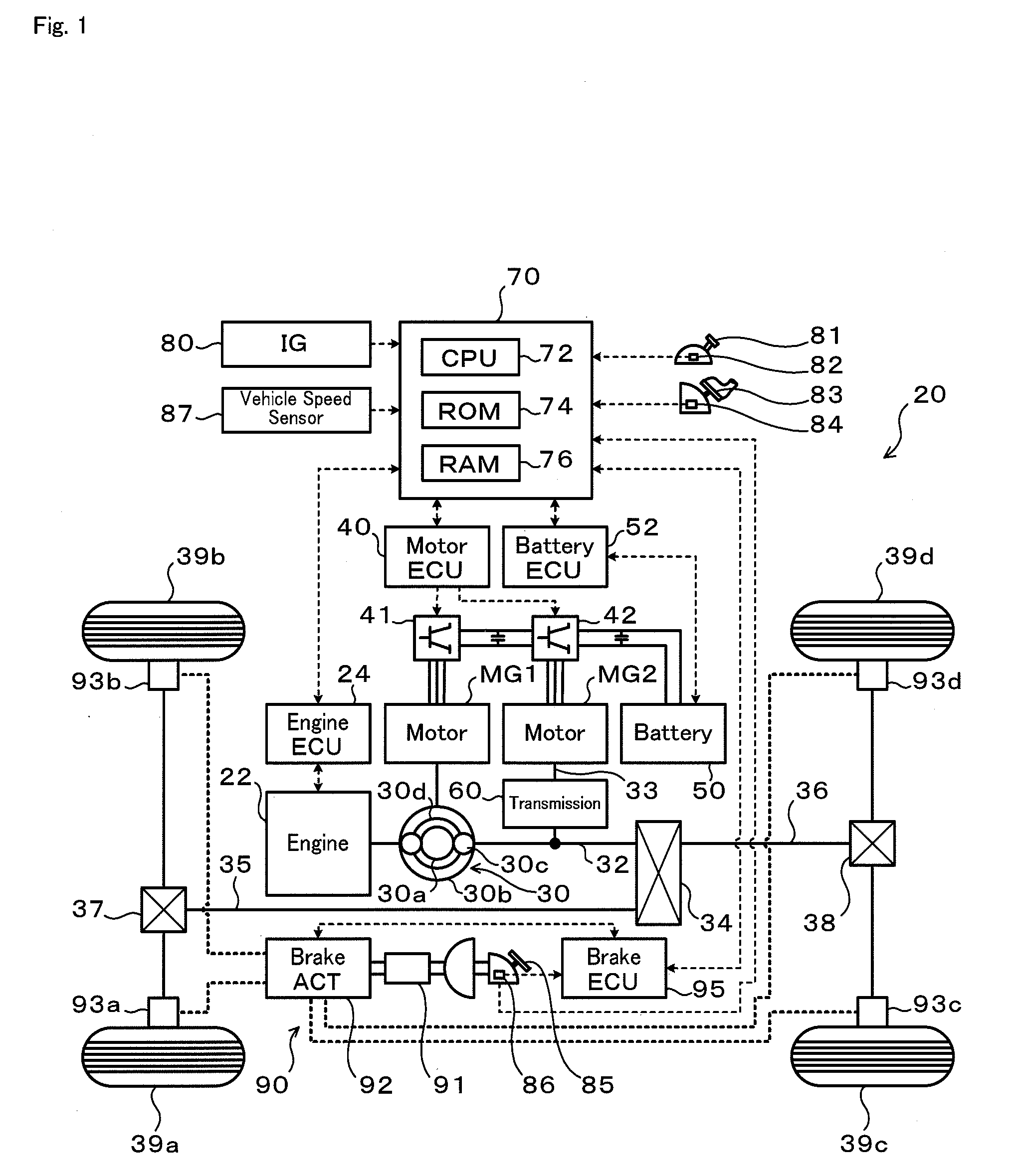
[0031]FIG. 1 schematically illustrates the configuration of a hybrid vehicle 20 equipped with a power output apparatus including a driving system according to one embodiment of the invention. The hybrid vehicle 20 shown in FIG. 1 is constructed as a 4-wheel drive vehicle and includes an engine 22, a three shaft-type power distribution integration mechanism 30 that is linked to a crankshaft or an output shaft of the engine 22 via a damper (not shown), a motor MG1 that is linked to the power distribution integration mechanism 30 and has power generation capability, a motor MG2 that is linked to the power distribution integration mechanism 30 via a transmission 60, a transfer 34 that transfers the output power of the power distribution integration mechanism 30 in a distributive manner to a front propeller shaft 35 as a first shaft and a rear propeller shaft


PUM


Abstract

In response to a driver's braking request operation, for example, the driver's depression of a brake pedal 85, a hybrid vehicle 20 sets a fraction of a regenerative braking torque by a motor MG2 and a fraction of a braking torque by a brake unit 90 relative to a preset braking torque demand Tr* according to the setting of a speed change ratio in a transmission 60 (steps S280, S290, S310, S320, S390, and S400). The hybrid vehicle 20 controls the motor MG2 to output the regenerative braking torque based on the preset braking torque demand Tr* and the set fraction of the regenerative braking torque, while controlling the brake unit 90 to enable the braking torque based on the preset braking force demand Tr* and the regenerative braking torque by the motor MG2 to be applied in a distributive manner at a preset front-rear braking torque distribution ratio ‘d’ to front wheels 39a and 39b and to rear wheels 39c and 39d.

Description


Claims


Application Information

Patent Timeline
Owner TOYOTA JIDOSHA KK
Why Eureka
Try Eureka