Arc Welder and Related System

a technology of arc welding and related systems, which is applied in the field of welding, can solve the problems of increased residual stress and distortion of the base metal being welded, increased welding penetration, and increased heat input of the base metal

Active Publication Date: 2008-08-14
ZHANG YU MING
View PDF16 Cites 42 Cited by
  • Summary
  • Abstract
  • Description
  • Claims
  • Application Information

AI Technical Summary

Benefits of technology

This patented describes methods used during welds that involve two different types of electric arcs: 1) direct-current (DC), which involves applying voltage directly across terminals; 2) alternating-voltage AC (AC). These techniques can be applied separately but they are often combined together into hybrid systems called inductive chargers.

Problems solved by technology

The technical problem addressed in this patents relates to improving the efficiency at producing high quality steel products through improved methods involving electric resistance weldings called Weld MAG® technology. Current techniques involve either slow down the winding speed of a single type of weld gun during production, resulting in decreased accuracy due to excess material on top surfaces. To address this issue, multiple types of wires may be added together but each has its own advantages and disadvantages compared to traditional monoeletron weld guns.

Method used


Image

  • Arc Welder and Related System
  • Arc Welder and Related System
  • Arc Welder and Related System

Examples


example 1

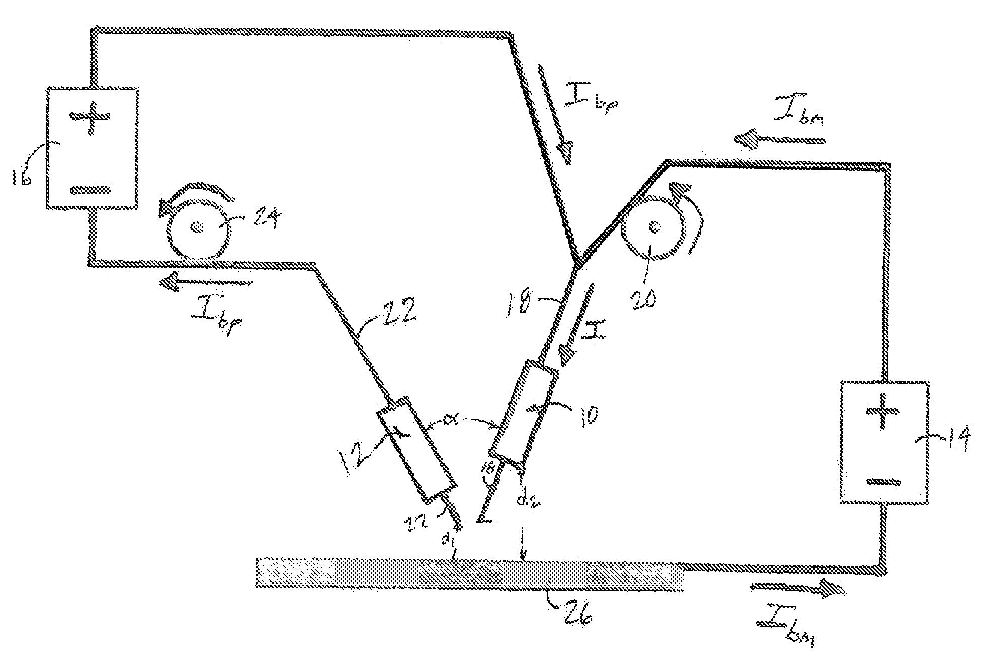
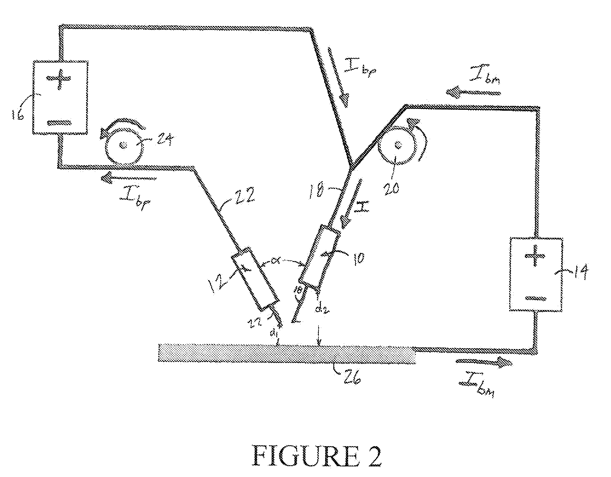
[0048]A welding system was setup with a CV power supply, a GMAW gun, a water-cooled GTAW torch, and four 0.1 ohm power resistors controlled by four IGBTs. The tungsten electrode, protected by a water cooling system, had a diameter of 3.2 mm. Pure argon was used to shield the GMAW gun and GTAW torch. The gas flow rates for the GMAW gun and GTAW torch were 16.5 L / min and 7.1 L / min, respectively. The following parameters were used to determine the geometrical relationship between the GMAW gun, GTAW torch, and base metal: the distance from the GMAW contact tube to the base metal was set to 20 mm; the distance from the bypass electrode to the base metal was set to 5 mm; the distance between the bypass electrode and the electrode wire was set to 4mm; and the angle between the electrode wire and the tungsten electrode was set to 60°. The base metal was a mild steel plate measuring 50×120×2 mm. A low-carbon welding wire (ER70S-6) with a diameter of 1.2 mm was used. The welding voltage was


PUM

PropertyMeasurementUnit
Electric potential / voltageaaaaaaaaaa
Poweraaaaaaaaaa
Electrical resistanceaaaaaaaaaa

Abstract

A welder for welding a base metal. The welder may include a first electrode for forming a first arc with the base metal and a second electrode for forming a second arc between the first and second electrodes. A compact welder, welding system, and method are also provided.

Description


Claims


Application Information

Patent Timeline
Owner ZHANG YU MING
Why Eureka
Try Eureka