Fixing device and image forming apparatus
a technology of fixing device and image forming apparatus, which is applied in the direction of electrographic process apparatus, instruments, optics, etc., can solve the problems of large space required for arranging the fixing device, unstable operation, and damage to the handl
- Summary
- Abstract
- Description
- Claims
- Application Information
AI Technical Summary
Benefits of technology
Problems solved by technology
Method used
Image


Examples
first embodiment
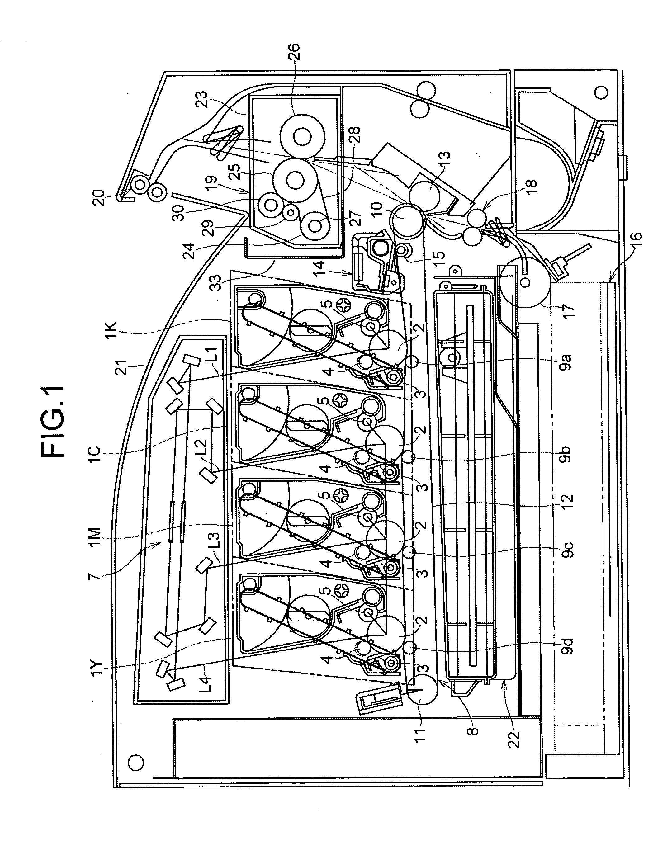
[0028]FIG. 1 is a schematic diagram of an image forming apparatus including a fixing device according to the present invention. The image forming apparatus includes four process units 1K, 1C, 1M, and 1Y. The process units 1K, 1C, 1M, and 1Y forms a color image by using developers of four primary colors, i.e., black, cyan, magenta, and yellow.
[0029]The process units 1K, 1C, 1M, and 1Y have the same configuration except that they contain toner of different colors. The process unit 1K will be described as an example. The process unit 1K includes an image carrier 2, a cleaning unit 3, a charging unit 4, and a developing unit 5. The process unit 1K is detachably attached to a main body of the image forming apparatus.
[0030]An exposure device 7 is arranged above the process units 1K, 1C, 1M, and 1Y. In the exposure device 7, laser beams L1 to L4 are emitted from laser diodes (not shown) based on image data.
[0031]A transfer belt device 8 is arranged under the process units 1K, 1C, 1M, and 1Y.
second embodiment
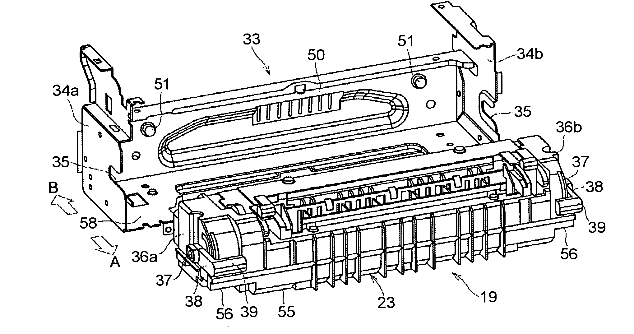
[0058]FIG. 9 is a perspective view of a fixing device 69 according to the present invention. The fixing device 69 includes a holding recession 76, and a plurality of convex portions 57 is arranged on the holding recession 76. Each of the convex portions 57 is a protruding portion that extends in a direction substantially orthogonal to a direction to which the housing 23 (fixing device 69) is attached to or detached from the holding frame member 33. The convex portions 57 are arranged parallel to each other. Because the convex portions 57 are arranged on the holding recession 76, it is possible to avoid a slip of the finger on the holding recessions 56 when the user holds the holding recession 76. The housing 23 is made of a resin or the like that has a relatively low thermal conductivity. However, the housing 23 may become hot due to heat generated upon a fixing operation performed by the fixing device 19. Even if the holding recession 76 becomes hot due to heating of the housing 23, t
third embodiment
[0060]FIG. 10 is a perspective view of a fixing device 79 according to the present invention. FIG. 11 is a side view of the fixing device 79. The fixing device 79 includes two protruding members 59, 59 that are formed on the front surface 60 of the housing 23: one near the right side, and the other near the left side. The protruding member 59 is a small rectangle member. The protruding member 59 is integrally formed on the front surface 60 in a protruding manner. The protruding member 59 is arranged between the operating member 39 and the holding recession 56. When the switching lever 38 swings down, the operating member 39 is in contact with the protruding member 59, so that the switching lever 38 is held in the disengage position. The fixing device 79 does not include the lower stopper 43 shown in FIG. 4. Detailed descriptions of the components in FIGS. 10, 11 with the same reference numerals as those in FIGS. 3, 4 are omitted, because they have the same configuration.
PUM
 Abstract
Description
Claims
Application Information
 - R&D Engineer
- R&D Manager
- IP Professional
- Industry Leading Data Capabilities
- Powerful AI technology
- Patent DNA Extraction
Browse by: Latest US Patents, China's latest patents, Technical Efficacy Thesaurus, Application Domain, Technology Topic.
© 2024 PatSnap. All rights reserved.Legal|Privacy policy|Modern Slavery Act Transparency Statement|Sitemap