Headset antenna and connector for the same

Active Publication Date: 2009-02-05
HTC CORP
View PDF8 Cites 46 Cited by
  • Summary
  • Abstract
  • Description
  • Claims
  • Application Information

AI Technical Summary

Benefits of technology

[0007]Accordingly, the present invention is directed to a mobile phone antenna, in which a high impedance element is disposed on a transmission path of an audio signal. The high impedance element is adapted to selectively increase equivalent impedance at a specified frequency band of the antenna. Therefore, the audio signal lines are equal to an open circuit at the specified frequency band of RF signals received by the antenna, and receiving capability of the antenna is improved.
[0008]The present invention provides a connector for an electronic device. There is a high impedance element disposed at a transmitting pin of audio signals so as to avoid a loss of the receiving capability of the antenna caused by circuit coupling.
[0019]The present invention disposes a high impedance element on a transmission path of an audio signal, an impedance of the high impedance element varying corresponding to the frequency. In such a way, the high impedance element is capable of selectively generating a greater equivalent impedance in the specified frequency band of an RF signal received by the antenna. As such, the audio line is regarded as an open circuit at the specified frequency band of the RF signal and as a short circuit at the specified frequency band of the audio signal, so that the audio signal can be well transmitted thereby. When the antenna receives an RF signal, the high impedance element that is equivalent to a high impedance element is capable of decreasing the coupling between the RF signal and the adjacent audio signal line, so as to improve the receiving capability of the antenna.

Problems solved by technology

That is so because, the audio signal line is equal to a ground at the specified frequency band of the RF (Radio frequency) signal, so that receiving capability of the antenna is weakened due to the adjacent audio signal lines.
This is also a main factor restricting the receiving capability of the current conventional headset antennas.

Method used


Image

  • Headset antenna and connector for the same
  • Headset antenna and connector for the same
  • Headset antenna and connector for the same

Examples


first embodiment

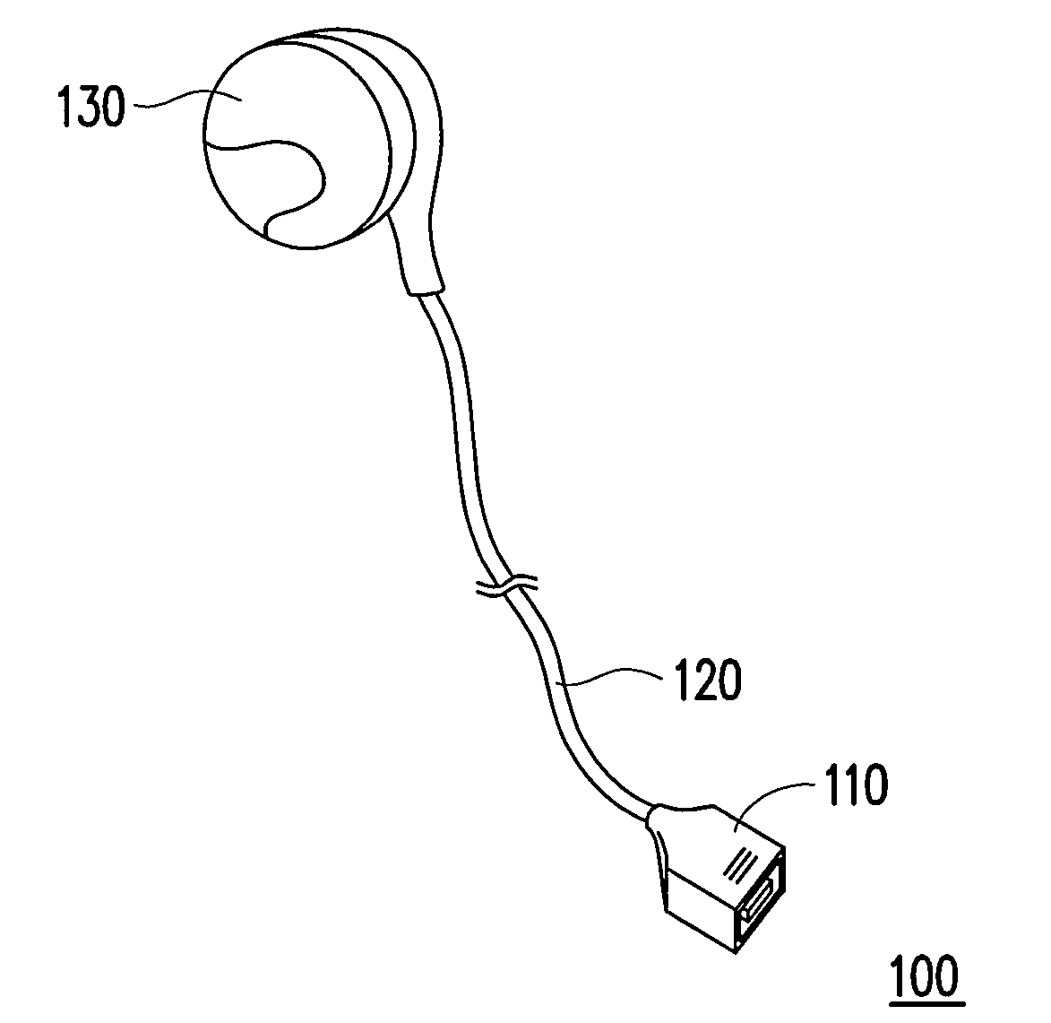
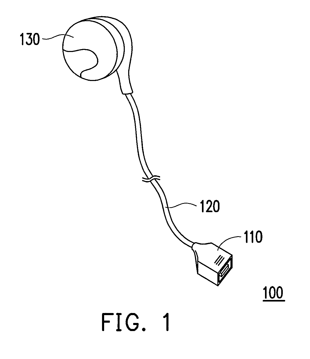
[0028]FIG. 1 illustrates a headset antenna according to a first embodiment of the present invention. Referring to FIG. 1, the headset antenna 100 includes a connector 110, a headset wire 120 and a speaker 130. The headset wire 120 may include a ground line for left / right sound channels, an audio signal line of a left sound channel, an audio signal line of a right sound channel, an audio signal line of a microphone, and an antenna. According to different types of products, the headset wire 120 may selectively integrates the audio signal lines of the left sound channel and the right sound channel, and the audio signal line of the microphone, or even more signal transmission lines, e.g., a signal line for controlling a volume adjustment. According to an aspect of the first embodiment, the headset wire 120 is exemplified as including a ground line for left / right sound channels, an audio signal line of the left sound channel, an audio signal line of the right sound channel, an audio sign...

second embodiment

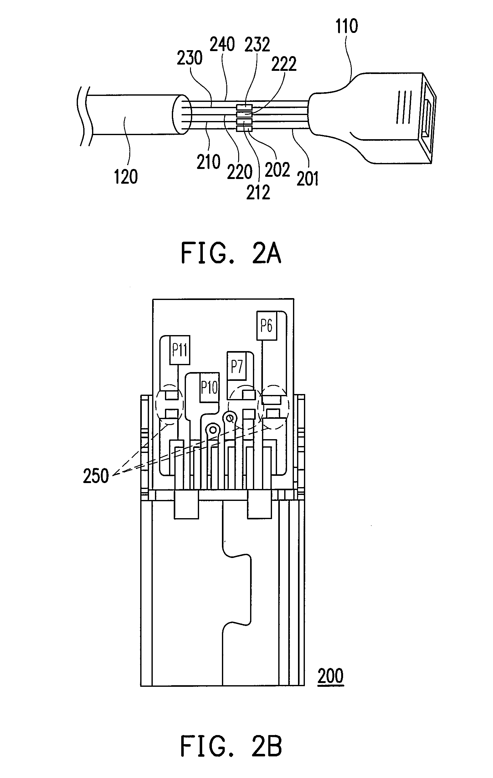
[0038]In another concern, the high impedance element can also be disposed on a board of the connector 110 as shown in FIG. 2B. FIG. 2B is a structural diagram illustrating a connector according to a second embodiment of the present invention. Referring to FIG. 2B, there is illustrated a contact portion 200 of the connector. The audio pin P6 is adapted for transmitting an audio signal of the microphone. The audio pin P7 is adapted for transmitting an audio signal of the right sound channel. The audio pin P11 is adapted for transmitting an audio signal of the left sound channel. The antenna pin P10 is adapted for transmitting the RF signal received from the antenna.

[0039]The high impedance elements can be disposed on the rears of respectively the audio pins P6, P7, P11 and directly integrated to the designed position 250 on the board of the connector. In an integrating process, the high impedance elements can be integrated to the substrate by a low temperature co-fired ceramic (LTCC) ...

third embodiment

[0045]FIG. 4 is a schematic structural diagram illustrating an electronic device and a connector thereof according to a third embodiment of the present invention. Referring to FIG. 4, the electronic device 400 includes a connector 450. The connector 450 includes pins 401, 410, 420, 430, 440. The pin 401 for example is a ground pin for grounding left and right sound channels corresponding to ground levels of the audio signals thereof. The pins 410 and 420 are for example audio pins of respectively the left and right sound channels for transmitting audio signals to the headset antenna 460. The pin 430 for example is a microphone audio pin for transmitting audio signals of the microphone. The pin 440 for example is an antenna pin, for transmitting RF signals received by the headset antenna 460. The headset antenna 460 is coupled to the electronic device 400 via the connector 450.

[0046]Each of high impedance elements 402, 412, 422, 432 is disposed at a rear of the pins 401, 410, 420, 43...


PUM


Abstract

A headset antenna and a connector for the same are provided. The headset antenna includes an audio signal line, an antenna and a high impedance element in specified application frequency ranges. The audio signal line is adapted for transmitting an audio signal and the antenna is adapted for receiving an RF signal. The high impedance element is disposed on a transmission path of the audio signal and generates a high impedance at a specified frequency band of the RF signal, so that the audio signal line is equivalent to an open circuit and the antenna obtains a better receiving capability.

Description

CROSS-REFERENCE TO RELATED APPLICATION[0001]This application claims the priority benefit of Taiwan application serial no. 96127761, filed on Jul. 30, 2007. The entirety of the above-mentioned patent application is hereby incorporated by reference herein and made a part of this specification.BACKGROUND OF THE INVENTION[0002]1. Field of the Invention[0003]The present invention generally relates to a circuit structural design for an antenna, and more particularly to a circuit structural design for a headset antenna.[0004]2. Description of Related Art[0005]Headset antennas are widely used in mobile broadcast, especially in receiving operation of frequency modulation (FM) broadcast. Currently, headset antennas are also employed in mobile television field for improving signal receiving efficiency thereof.[0006]In a typical headset antenna, an audio signal line and an antenna are often integrated in a headset wire. Therefore, signals received by the antenna attenuate due to a coupling effe...

Claims


Application Information

Patent Timeline
IPC IPC(8): H01Q1/27H01Q1/50H01Q1/00
CPCH01Q1/52H01Q1/273
Inventor HUNG, CHUNG-TING
Owner HTC CORP
Why Eureka
Try Eureka