Electric discharge machine and electric discharge machining method

a technology of electric discharge machine and machining method, which is applied in water/sewage treatment, water/sludge/sewage treatment, chemistry apparatus and processes, etc., can solve problems such as deterioration of workpiece quality, and achieve the effect of preventing corrosion of workpieces

Inactive Publication Date: 2009-03-05
MITSUBISHI ELECTRIC CORP
View PDF5 Cites 5 Cited by
  • Summary
  • Abstract
  • Description
  • Claims
  • Application Information

AI Technical Summary

Benefits of technology

The present invent describes an anti-corrosive method for protecting metal surfaces against damage due to chemical reactions between them without requiring high voltages that could cause it over time. This results in improved durability compared with traditional methods such as electroplating or painting on steel plates.

Problems solved by technology

This patents describes methods for producing high purity water containing specific types of ions called oxygen ions without damaging metals like iron. These techniques involve adding certain substances to increase their solubility in pure water, allowing them to form complexes with other charged particles. By doing these processes, it becomes possible to remove unwanted materials out of solution. Additionally, some embodiments include controlling the acid content within the liquid itself based upon factors like temperature and pressure conditions.

Method used


Image

  • Electric discharge machine and electric discharge machining method
  • Electric discharge machine and electric discharge machining method
  • Electric discharge machine and electric discharge machining method

Examples


first embodiment

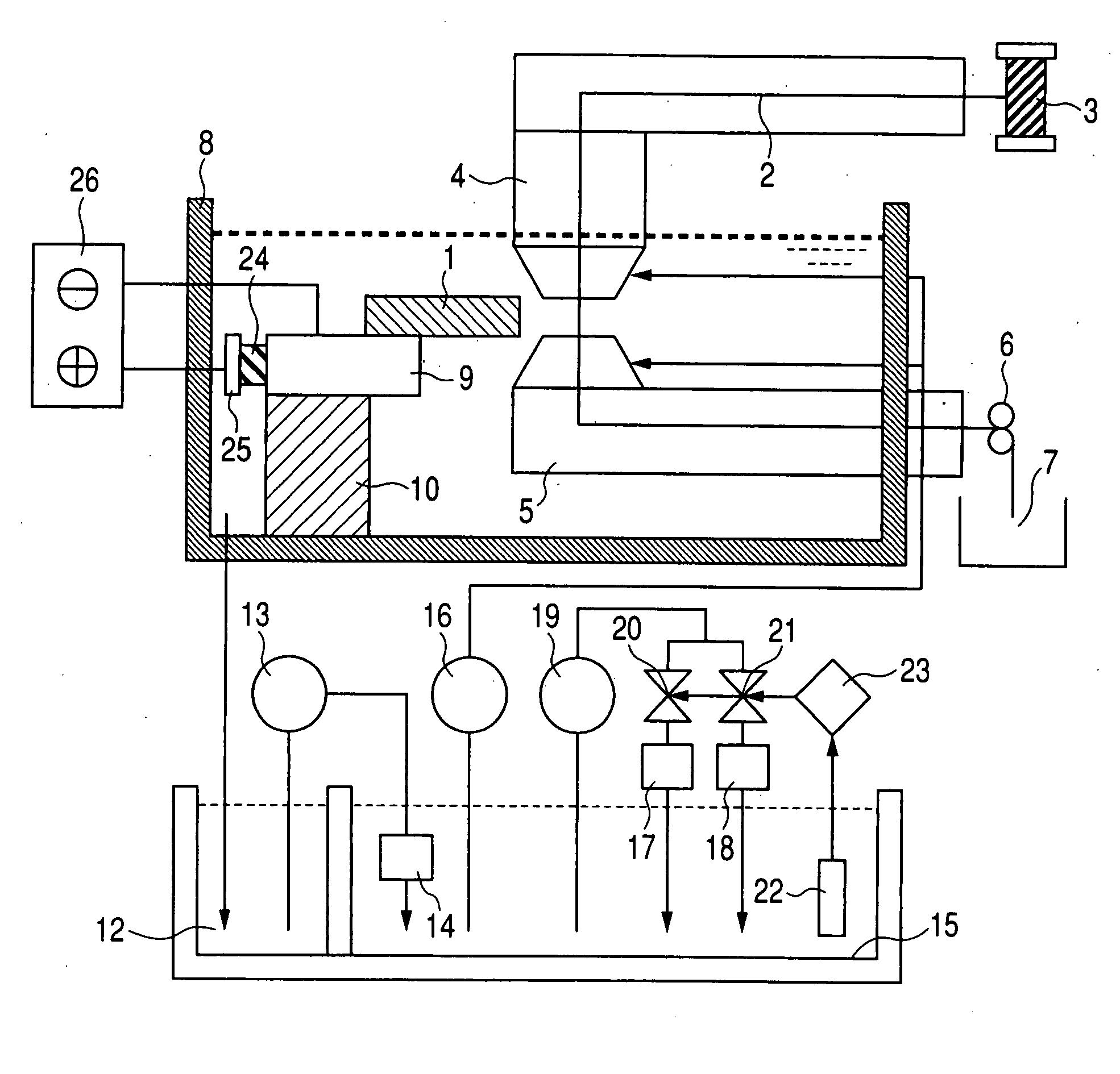
[0023]FIG. 1 is a block diagram showing an electrical wire discharge machine according to a first embodiment of the present invention. The electrical wire discharge machine proceeds with machining by applying a voltage between a workpiece 1 and a wire electrode 2 within a working tank 8; and causing an electrical discharge through a dielectric fluid squirted from an upper dielectric fluid nozzle 4 and a dielectric fluid squirted from a lower dielectric fluid nozzle 5, to thus fuse and eliminate the target areas of the workpiece 1.

[0024]At this time, an electrical discharge portion of the wire electrode 2 is also fused / deteriorated in accordance with a progress in electrical discharge operation. Accordingly, the wire electrode 2 wound around a wire bobbin 3 is continuously fed to a recovery box 7 through the upper dielectric fluid nozzle 4, the lower dielectric fluid nozzle 5, and a recovery roller 6 so that a new wire electrode 2 is fed to the machining section in association with a

second embodiment

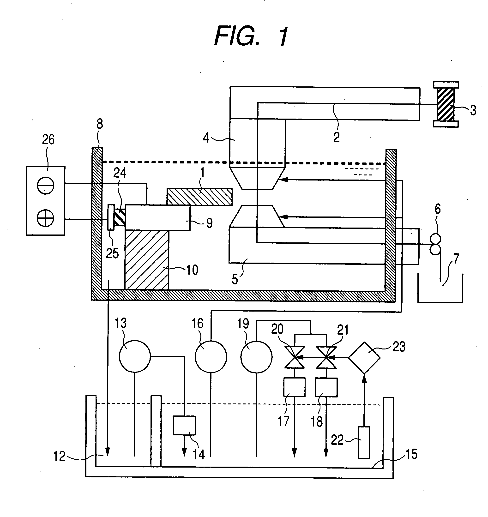
[0061]In the present embodiment, the working tank 8 is imparted with the function of the anticorrosive electrode as shown in FIG. 5.

[0062]According to the configuration, the working tank 8 and the table 9 are insulated from each other by the mount 10. The dielectric fluid exists between the working tank 8 and the table 9. Hence, the insulator 24 becomes obviated. Further, the area of the electrode is wide, and hence the electrical resistance of the electrode is lowered, which in turn enables a reduction in voltage and current.

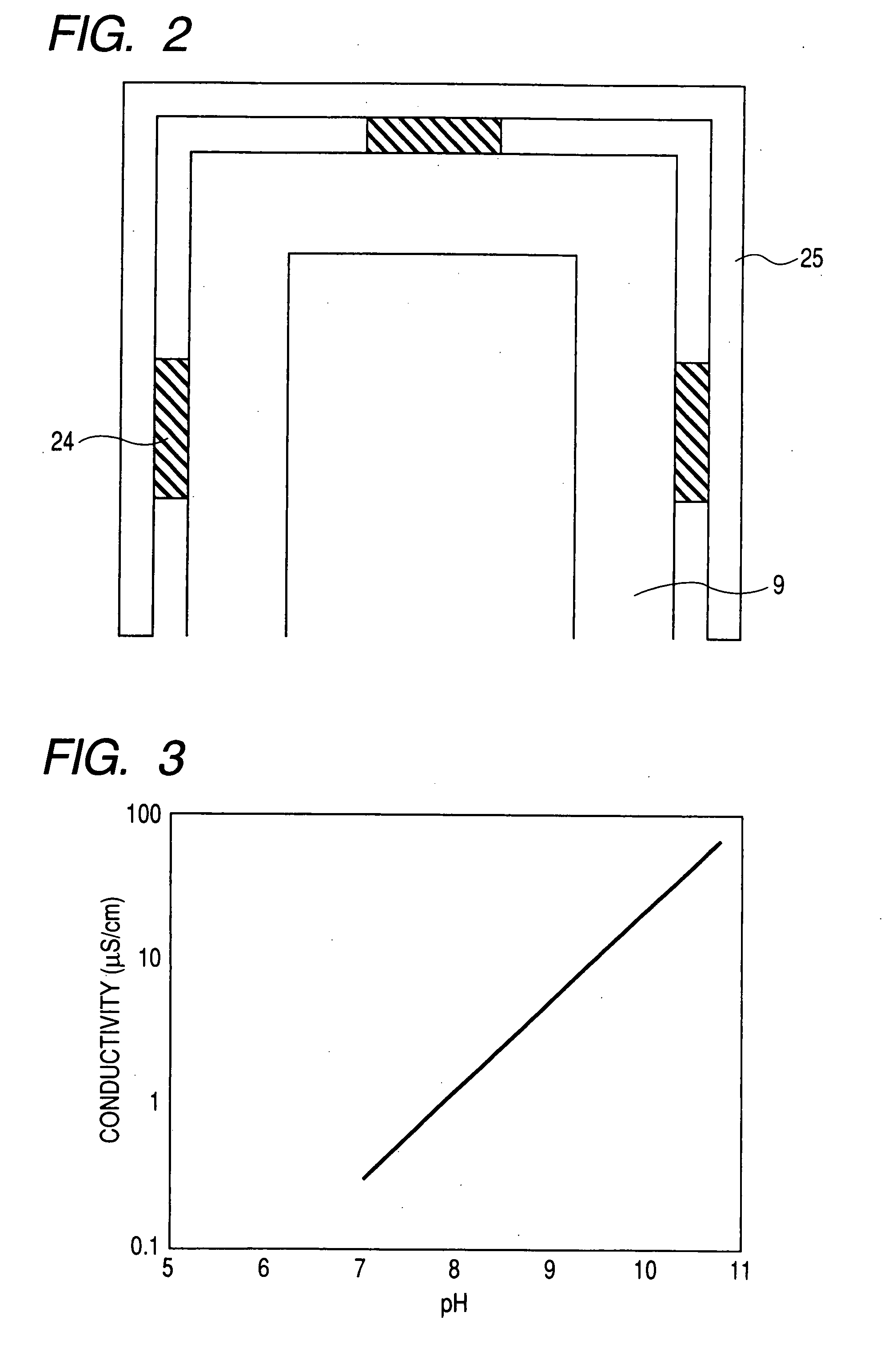
[0063]By the wire electrical discharge machine having the method for preventing corrosion of a workpiece, which would otherwise be caused by application of the voltage, the conductivity of the dielectric fluid was controlled to 6.2 μS / cm (corresponding to a pH value of 9.0). Further, a voltage of 3 volts was applied between the table 9 and the working tank 8. Thus, corrosion of a superhard material (WC-Co) or an iron-based material (SKD-11) was prevented during


PUM

PropertyMeasurementUnit
Electric potential / voltageaaaaaaaaaa
Electrical conductivityaaaaaaaaaa
Electric potential / voltageaaaaaaaaaa

Abstract

In an electric discharge machining apparatus that machines a workpiece (1) by using a water-based dielectric fluid as a dielectric fluid while a voltage is being applied to a machining gap between an electrode (2) and the workpiece (1), the electric discharge machine includes:
an anticorrosive power source section (26) that applies a predetermined voltage by taking the workpiece (1) as a cathode and taking as an anode an anticorrosive electrode (25) opposing the workpiece (1) with an insulator (24) therebetween;
a dielectric fluid quality measuring instrument (22) that measures a quality of the dielectric fluid; and
a dielectric fluid quality control section (16, 17, 18, 19, 20, 21, 23) that controls a pH level of the dielectric fluid to be within a range from 8.5 to 10.5 on the basis of the measured result of the dielectric fluid quality measuring instrument (22).

Description


Claims


Application Information

Patent Timeline
Owner MITSUBISHI ELECTRIC CORP
Why Eureka
Try Eureka