Optical arrangement and a microscope

Inactive Publication Date: 2009-03-05
LEICA MICROSYSTEMS CMS GMBH
View PDF13 Cites 2 Cited by
  • Summary
  • Abstract
  • Description
  • Claims
  • Application Information

AI Technical Summary

Benefits of technology

[0005]Accordingly, the task of the present invention is to provide an optical arrangement and a microscope of the aforementioned

Problems solved by technology

Depending on the optical assembly used, the known optical arrangements are very prone to field curvatures in

Method used


Image

  • Optical arrangement and a microscope
  • Optical arrangement and a microscope
  • Optical arrangement and a microscope

Examples


Embodiment Construction

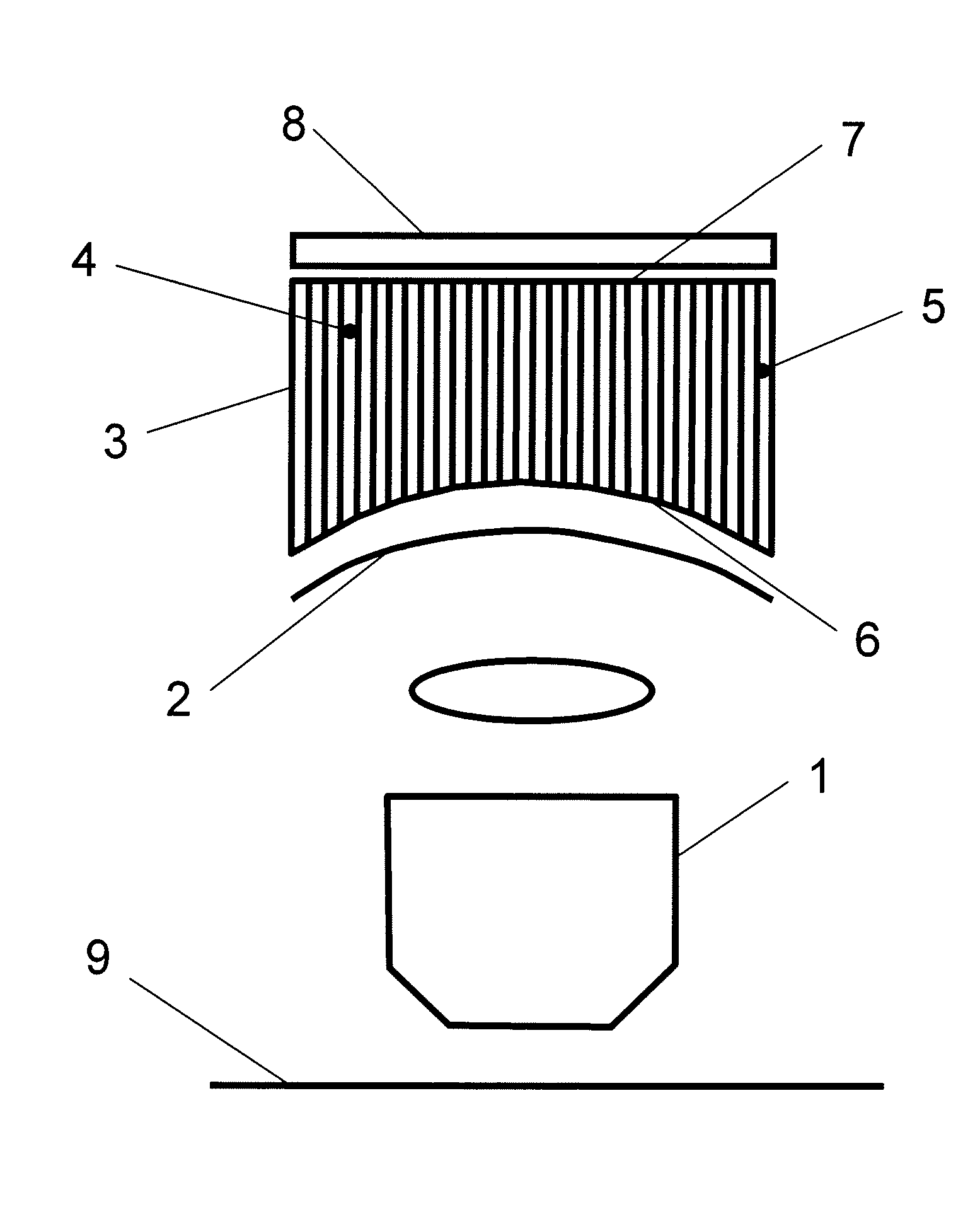
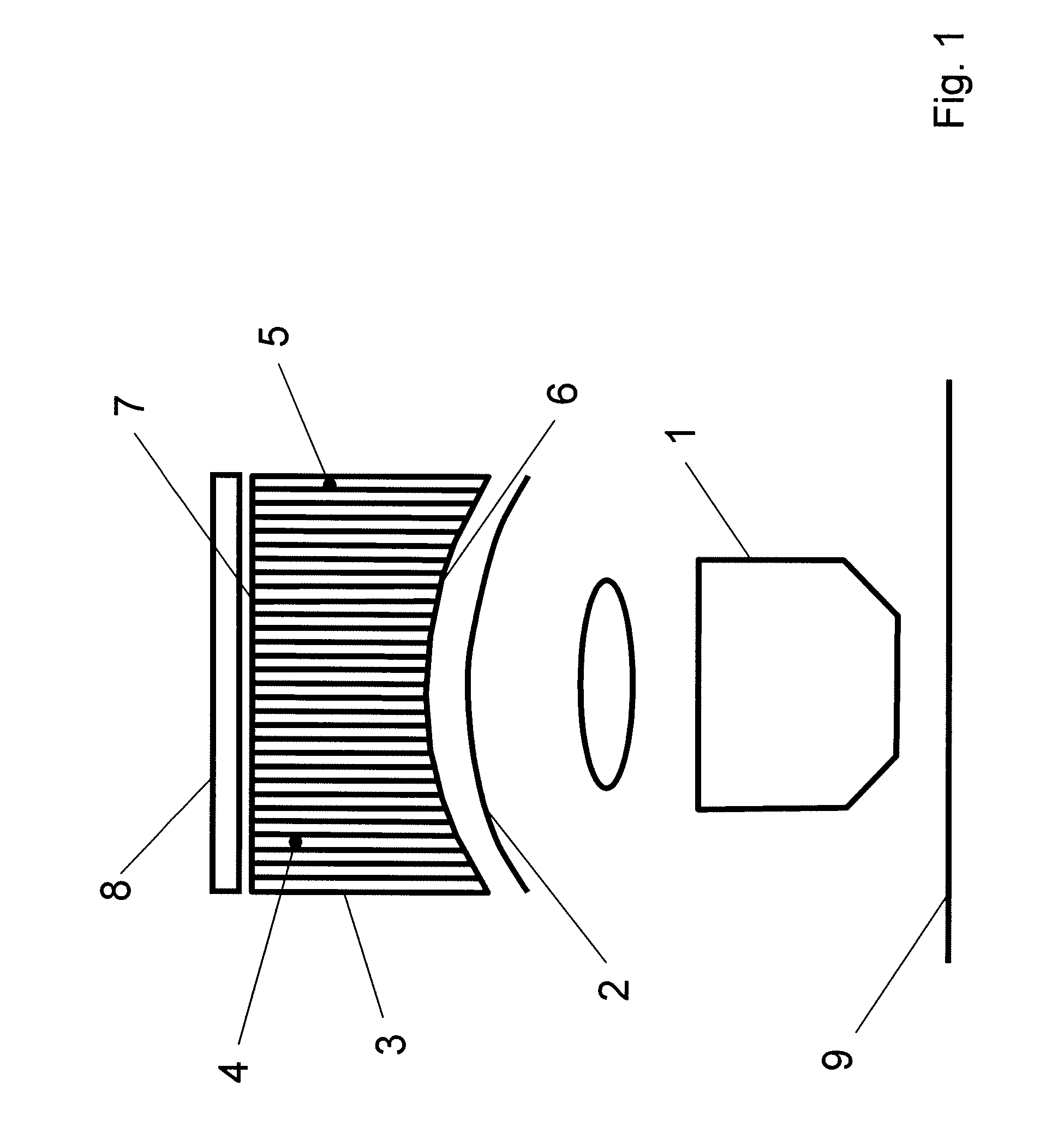
[0029]FIG. 1 shows an embodiment of an optical arrangement according to the invention having an optical component 1 for generating an intermediate image 2 in a beam path. With regard to a compensation or reduction of a field curvature with the aid of simple structural means, an optical element 3 having a plurality of optical waveguides 4 is arranged in the beam path after the intermediate image 2 to enable the imaging of the intermediate image 2 in a plane on a zone-by-zone or point-by-point basis.

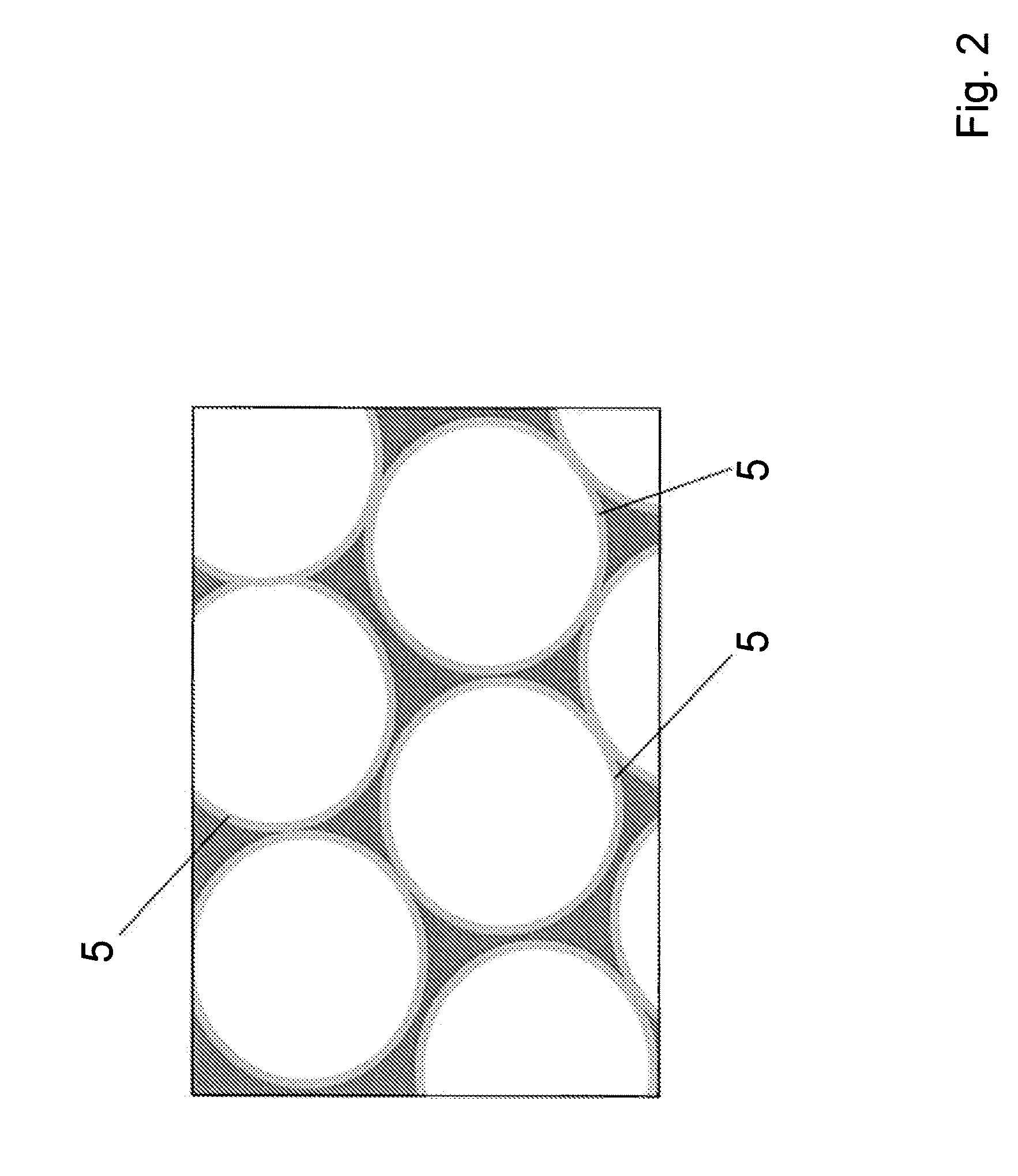
[0030]The optical waveguides 4 are arranged in parallel and next to each other and are formed as capillaries 5 or preferably as micro-capillaries. As a result, the intermediate image 2 is imaged in a plane on a quasi point-by-point or zone-by-zone basis. A curvature of the intermediate image 2 is thereby compensated.

[0031]The input end 6 of the optical element 3 is adapted to the curvature of the intermediate image 2. The output end 7 of the optical element 3 has a planar form.

[0032]At the ou


PUM


Abstract

An optical arrangement having an optical assembly (1) for generating an intermediate image (2) in a beam path is configured and further developed such that an optical element (3) having a plurality of optical waveguides (4) is arranged in the beam bath after the intermediate image (2) to enable the imaging of the intermediate image (2) in a plane on a zone-by-zone or point-by-point basis. Further, a microscope exhibiting such an optical arrangement is specified.

Description


Claims


Application Information

Patent Timeline
Owner LEICA MICROSYSTEMS CMS GMBH
Why Eureka
Try Eureka