LED unit and LED module

Inactive Publication Date: 2009-04-23
KEEPER TECH
View PDF5 Cites 44 Cited by
  • Summary
  • Abstract
  • Description
  • Claims
  • Application Information

AI Technical Summary

Benefits of technology

[0010]A light emitting diode (LED) unit in accordance with the present invention comprises a pair of substrates, an LED and a pair of brackets. The substrates are separated from and serve respectively as positive and negative electrodes. The LED is mounted on the substrates and has a pair of terminals mounted respectively on the substrates. The brackets serve respectively as positive and negative electrodes, ar

Problems solved by technology

However, the plastic bracket is not pliable or flexible and may only fitted in a corresponding vehicle light cavity.
Furthermore, mounting the w

Method used


Image

  • LED unit and LED module
  • LED unit and LED module
  • LED unit and LED module

Examples


first embodiment

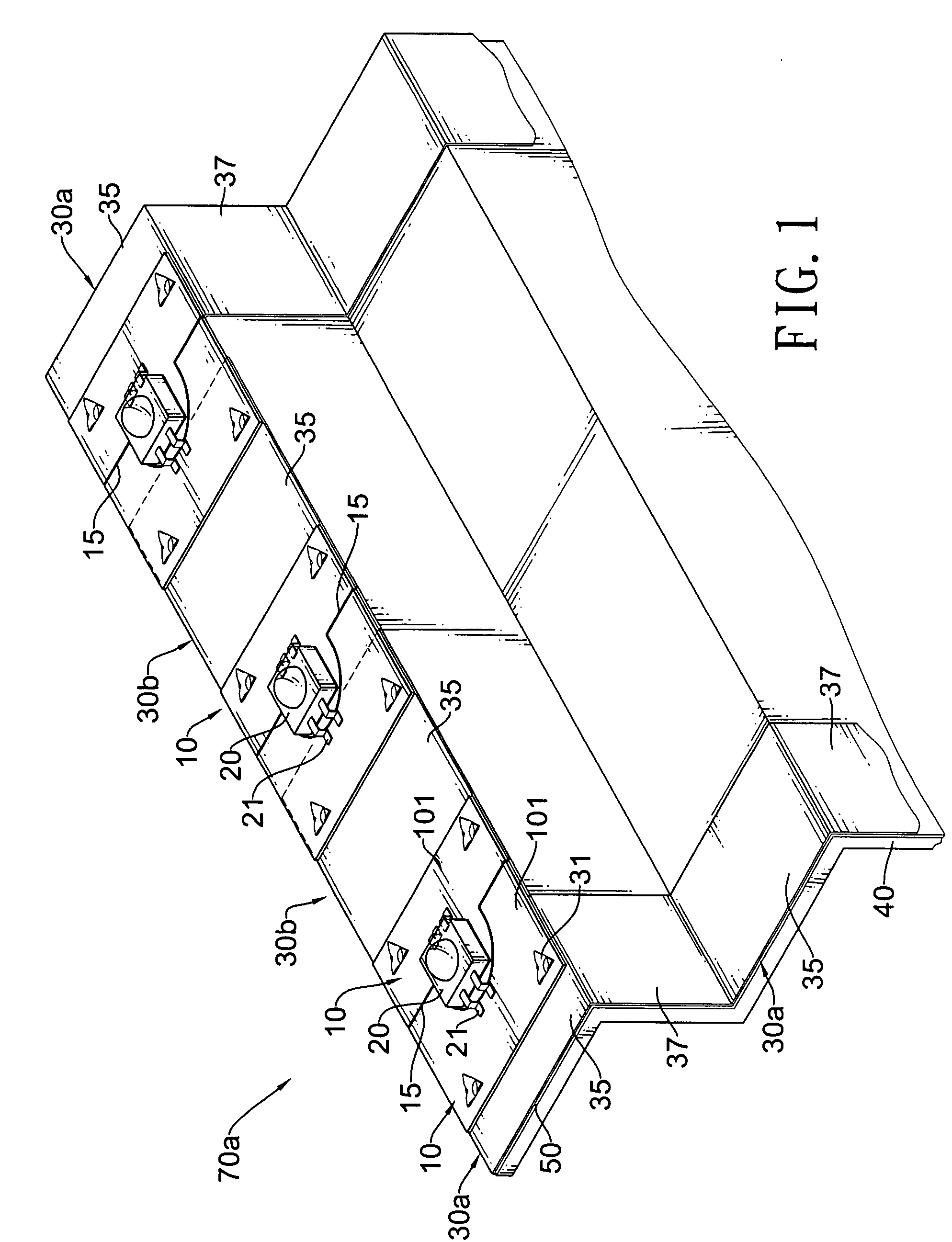
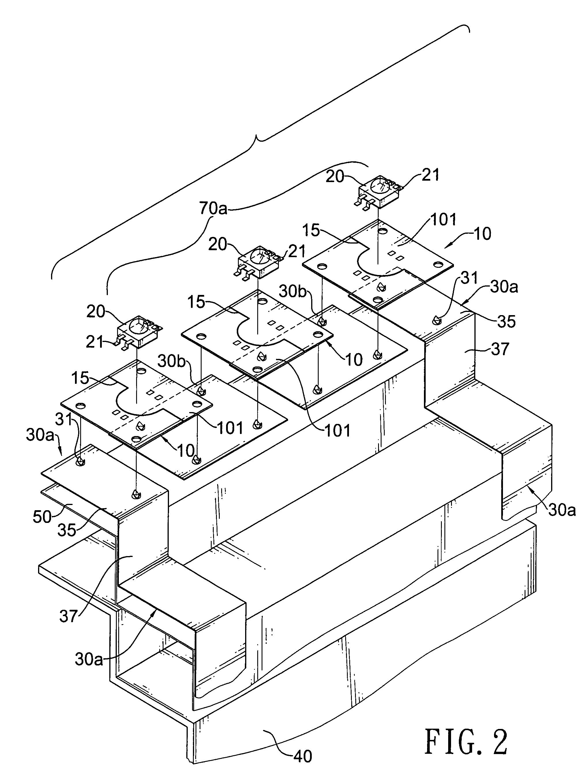
[0018]With reference to FIGS. 1, 2 and 3A, the LED module (70a) comprises multiple LED units (60). Each LED unit (60) comprises a pair of substrates, an LED (20), a pair of brackets (30a, 30b) and may further have a heat sink (40) and a heat-sink insulation layer (50).

[0019]The substrates (10, 10a), being electrically conductive, are separated from each other by a gap (15) and serves respectively as positive and negative electrodes. Each substrate (10, 10a) may further have a base and an insulation layer (101) and multiple mounting holes (102).

[0020]The base, being electrically conductive, has an outer surface and an inner surface. The inner surface is opposite to the outer surface. A first variant of the base is a copper base (103) formed into a single piece. With further reference to FIGS. 3B, a second variant of the base is laminated and has an aluminum board (106) and a copper board (105). The copper board (105) is attached to he aluminum board (106).

[0021]The insulation layer (101

second embodiment

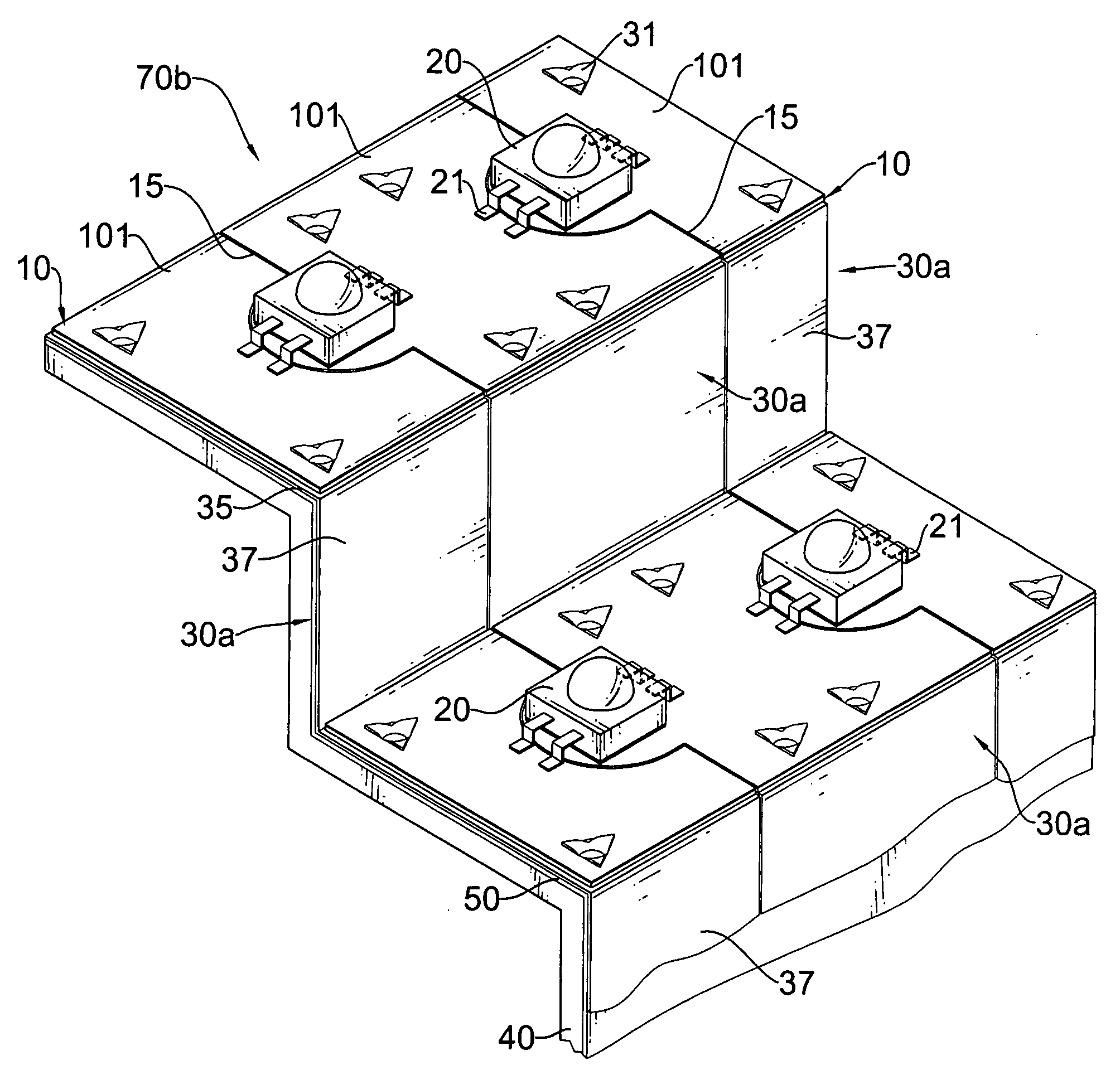
[0026]In a second embodiment, both the brackets (30a) of each LED units (60) are 3D brackets, as shown in FIGS. 4 and 5.

[0027]The 3D bracket of each LED unit (60), being non-flat, may be stepped, inclined or curved, is mounted one of the substrates (10, 10a), may be mounted on adjacent substrates (10, 10a). The 3D brackets of the LED units (60) are connected integrally to one another to form at least one 3D bracket module being non-flat, serving as at least one positive or negative electrode and holding a number of the LEDs (20). Each 3D bracket module is connected to some of the LEDs (20). In the first embodiment, two 3D brackets are arranged on opposite sides of the LED modules (70a). In the second embodiments, three 3D brackets are arranged in the LED modules (70b). Semi-finished 3D bracket modules may be a flat board manufactured by a single processing. Furthermore, the semi-finished 3D bracket modules are further formed into finished 3D bracket modules with different configuration


PUM


Abstract

A light emitting diode (LED) unit has a pair of substrates, an LED and a pair of brackets. The substrates are separated from and serve respectively as positive and negative electrodes. The LED is mounted on the substrates and has a pair of terminals mounted respectively on the substrates. The brackets serve respectively as positive and negative electrodes, are made of pliable and flexible metal and are mounted respectively on and electrically connected respectively to the substrates. At least one of the brackets serves as at least one three-dimensional (3D) bracket being non-flat. The 3D brackets are easily customized into various configurations by bending or stamping semi-finished 3D brackets to fit internal chambers or cavities of different lights such as vehicle lights. Accordingly, the cost of the LED modules is effectively lowered.

Description


Claims


Application Information

Patent Timeline
Owner KEEPER TECH
Why Eureka
Try Eureka