Solenoid device, automatic document feeder, and image forming apparatus
a solenoid device and automatic document feeder technology, applied in adaptive control, magnetic bodies, instruments, etc., can solve the problems of complex circuit devices, increased manufacturing costs, and insufficient reduction of impact noise, so as to achieve sufficient reduction of impact noise made by the plunger displacement, the effect of simple structur
- Summary
- Abstract
- Description
- Claims
- Application Information
AI Technical Summary
Benefits of technology
Problems solved by technology
Method used
Image

Examples
first embodiment
[0026]the present invention is hereinafter described in detail with reference to the drawings. A solenoid device 1 of this embodiment is provided in an automatic document feeder 32. As shown in FIG. 8, the automatic document feeder 32 has a document stack stage 2 on which a bundle of documents P are inserted and set. On the downstream side of the document stack stage 2, there are provided a pick-up roller 4 capable of sending out the bundle of documents P set on the document stack stage 2 to the downstream side, and a separation paper feeder unit 12 capable of separating and feeding the documents one by one. On the downstream side of the separation paper feeder unit 12, there is provided a first transfer path 21 capable of transferring the document P fed by the separation paper feeder unit 12 to an image read unit 10. On the downstream side of the image read unit 10, there is provided a second transfer path 22 capable of transferring the document P which came through the image read uni
second embodiment
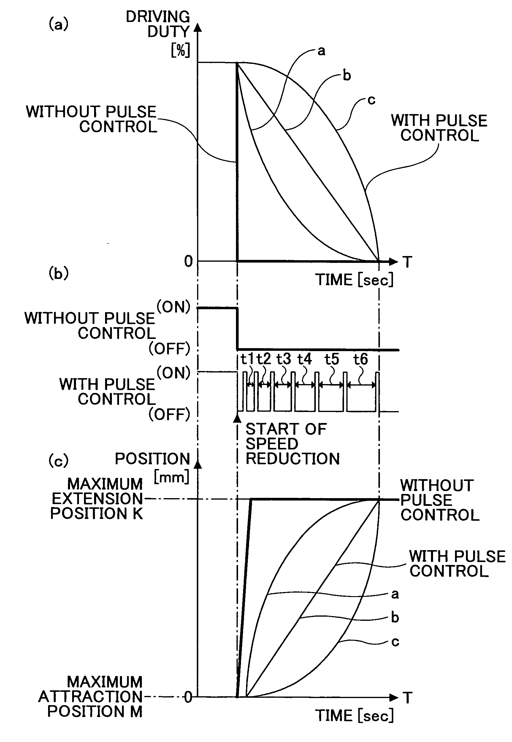
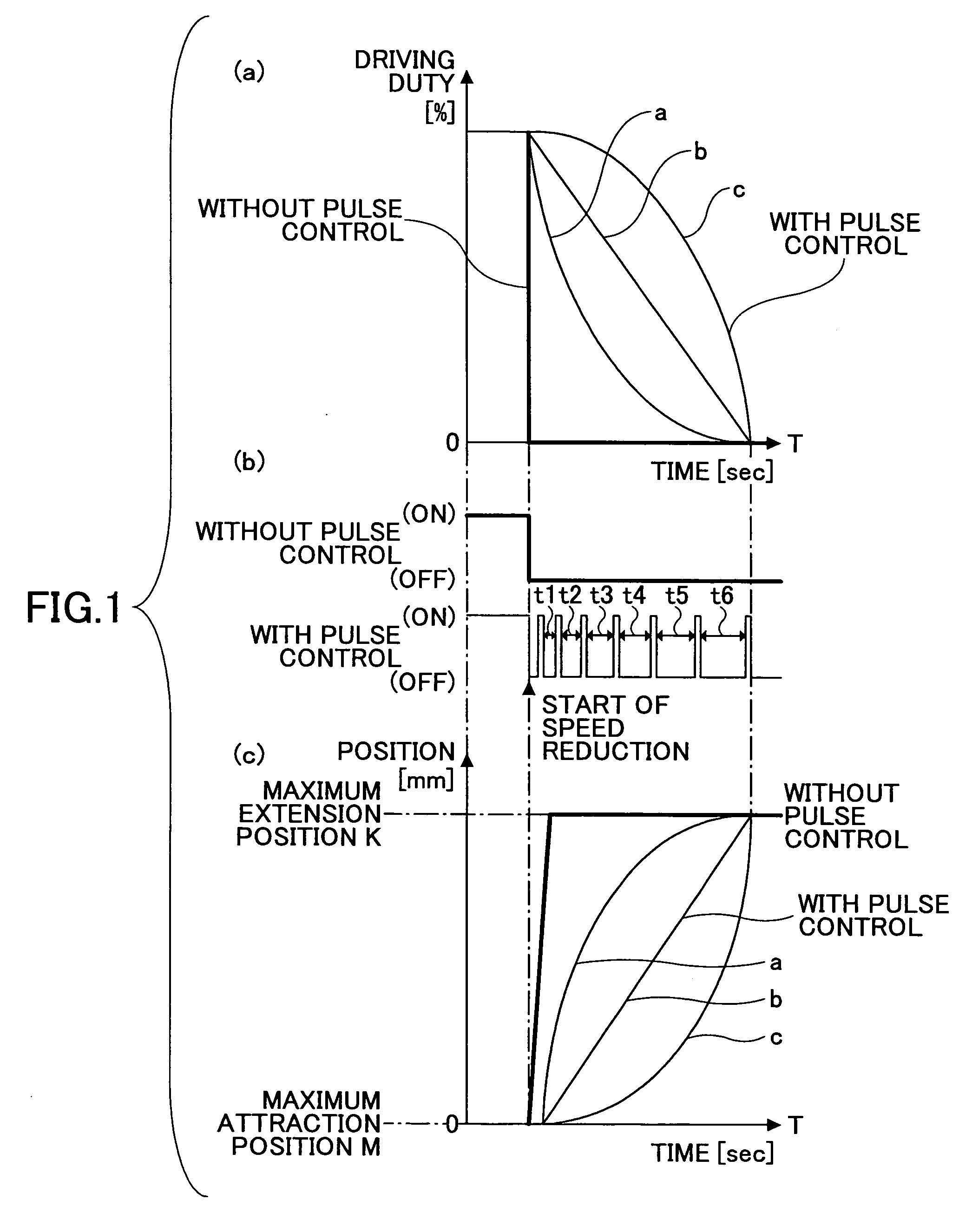
[0072]Hereinafter, a second embodiment is described with reference to FIGS. 10A and 10B. When the plunger 36 extends from the solenoid 43 side, as shown in FIG. 10A, the driving control unit 57 has plural pulse groups each formed of plural pulses with a constant pulse interval t (constant driving duty ratio). The pulse intervals t are set to be gradually longer per group. During a time between T1 and T2, there is a pulse group with a constant pulse interval t10. In a time between T2 and T3, there is a pulse group with constant pulse interval t11. In a time between T3 and T4, there is a pulse group with a constant pulse interval t12. In this manner, the pulse intervals are gradually longer per pulse group (t101112).
[0073]Further, when the plunger 36 is attracted into the solenoid 43 side, as shown in FIG. 10B, the driving control unit 57 includes plural pulse groups formed of plural pulses with a constant pulse interval t (constant driving duty ratio). The pulse intervals t are set to b
third embodiment
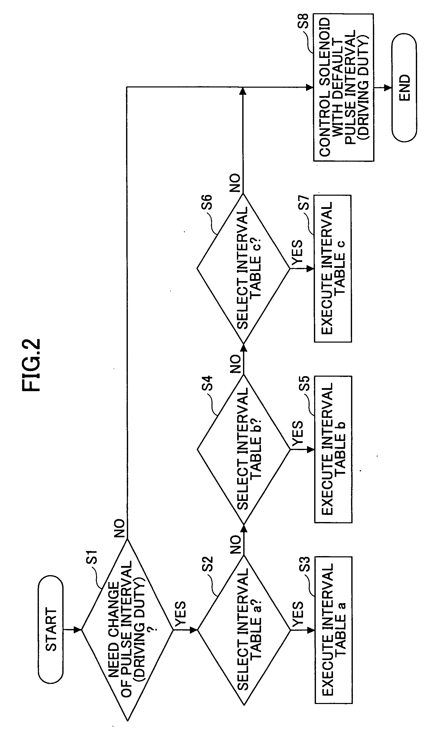
[0077]Hereinafter, a third embodiment is described with reference to FIGS. 11 and 12. In this embodiment, the voltage sensor 75 is not provided. Moreover, the interval table selection unit 65 is not provided in the driving control unit 57 as shown in FIG. 11. The interval table 62 (any one of the interval tables a, b, and c in this embodiment) can be selected by pressing an interval table selection button 81 (see FIG. 12) of an operation panel 25 (see FIGS. 9 and 12) of the image forming apparatus body 31. Then, the selected interval table is displayed on an operation display 83 (for example, “a” is displayed when the interval table a is selected).
[0078]That is, by sending a selection signal from the operation unit 73 in the image forming apparatus body 31 to the interval table storage unit 63, an execution signal is sent through the sending unit 71 to the solenoid 43, whereby the interval table execution unit 67 executes the selected interval table. When none of the interval tables 62
PUM
 Abstract
Description
Claims
Application Information
 - R&D Engineer
- R&D Manager
- IP Professional
- Industry Leading Data Capabilities
- Powerful AI technology
- Patent DNA Extraction
Browse by: Latest US Patents, China's latest patents, Technical Efficacy Thesaurus, Application Domain, Technology Topic.
© 2024 PatSnap. All rights reserved.Legal|Privacy policy|Modern Slavery Act Transparency Statement|Sitemap