Optical Pickup Device and Optical Disc Apparatus
- Summary
- Abstract
- Description
- Claims
- Application Information
AI Technical Summary
Benefits of technology
Problems solved by technology
Method used
Image

Examples
first embodiment
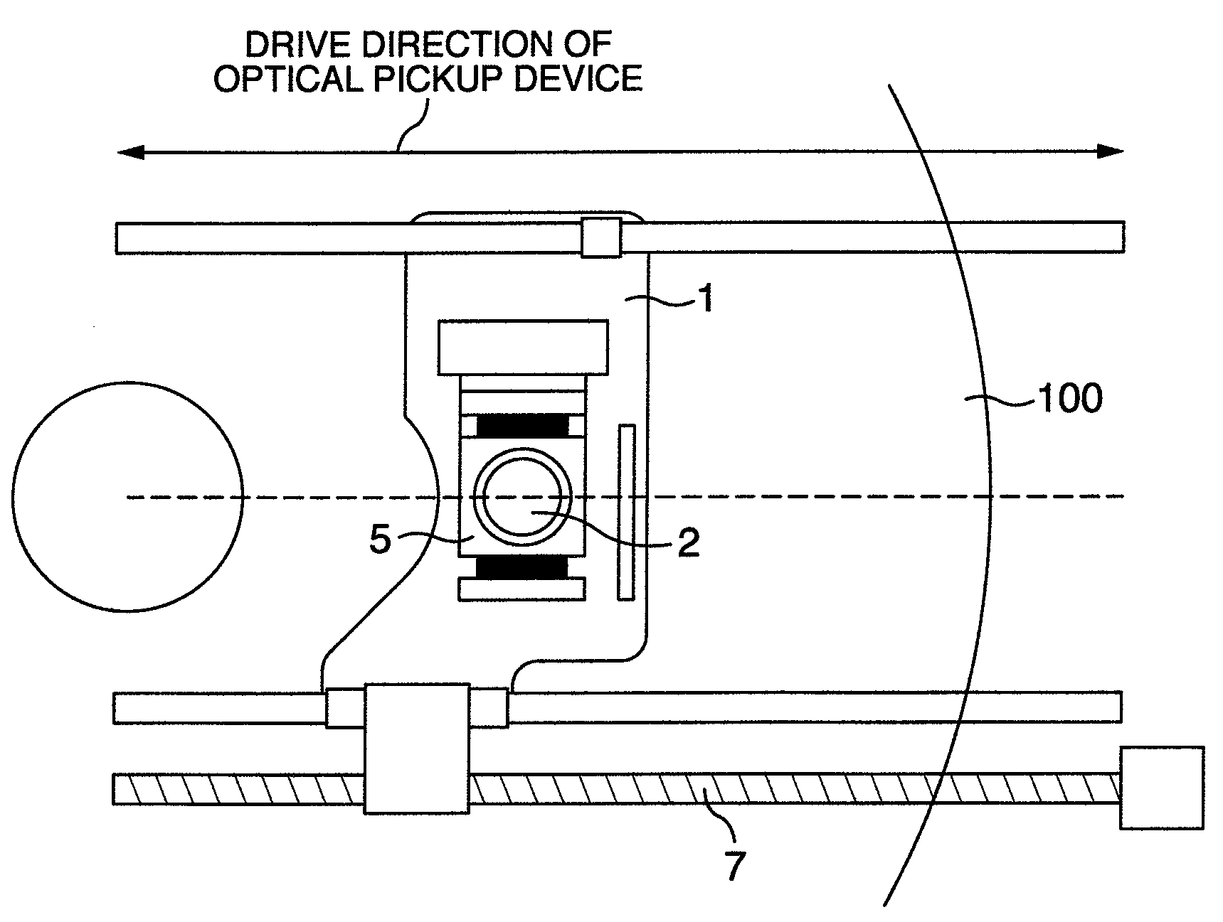
[0028]FIG. 1 shows an example of an optical pickup device according to the first embodiment of the present invention.
[0029]An optical pickup device 1 is structured in such a manner that the device can be driven in a Rad direction (see FIG. 3) of an optical disc 100 by a drive mechanism 7 shown in FIG. 1. An objective lens 2 is mounted on an actuator 5 of the optical pickup device, and radiates light to the optical disc. Light emitted from the objective lens 2 forms a spot on the optical disc 100 and is reflected from the optical disc 100. By detecting this reflected light, a focusing error signal and a tracking error signal are generated.
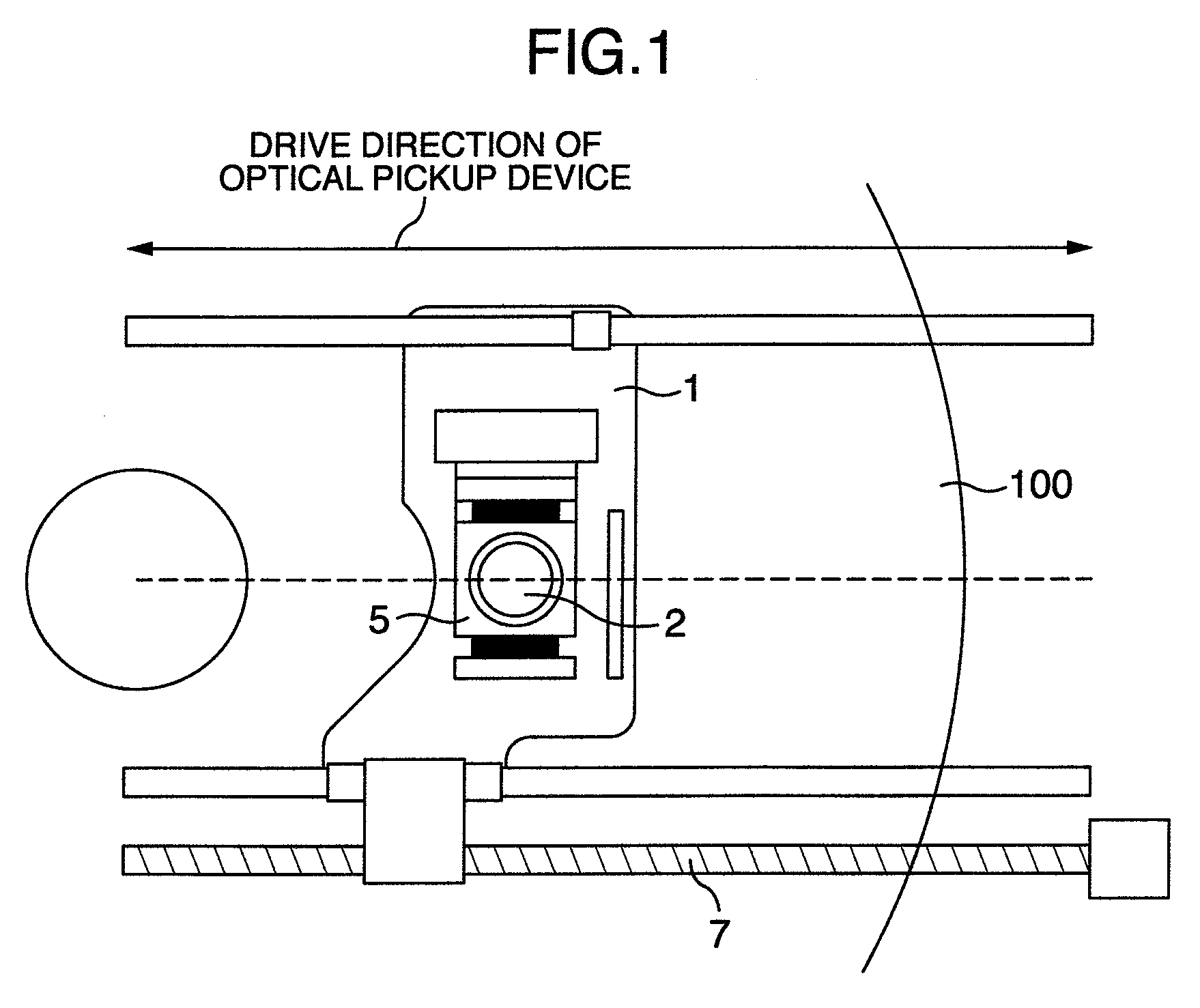
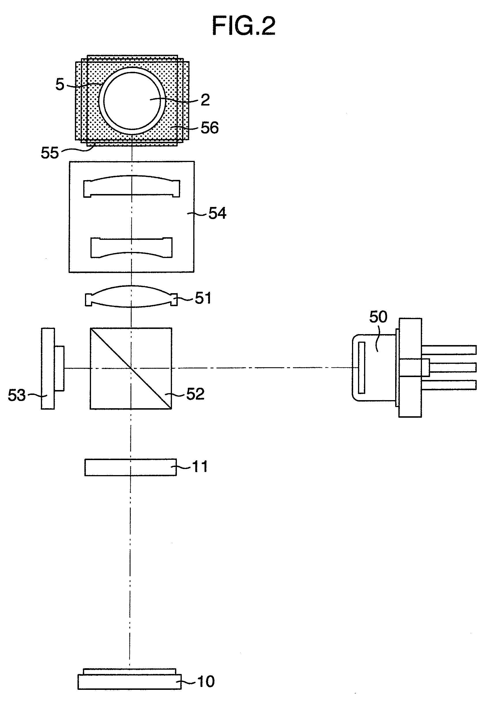
[0030]FIG. 2 shows an optical system of the optical pickup device described above. Although BD (Blu-ray Disc) will be described, other recording methods may also be used including HD (High Definition) DVD.
[0031]An optical beam having a wavelength of about 405 nm is emitted as radiation light from a semiconductor laser diode 50. The optical beam emitted
second embodiment
[0046]FIG. 10 shows a photodetector of an optical system of an optical pickup device according to the second embodiment of the present invention. Different points from the first embodiment reside in that the diffraction direction and the diffraction angle of each area of the diffraction grating 11 are different and the layout of light receiving parts of the photodetector 10 is different, and other structures are similar to those of the first embodiment.
[0047]The diffraction grating 11 has a pattern such as shown in FIG. 3. A solid line indicates a border of each area, a two-dot chain line indicates a circumferential shape of an optical flux of the laser beam, and hatched areas indicate a push-pull pattern formed by a track of the optical disc. A spectral ratio of the area of the diffraction grating 11 other than the Di area is, for example, (0-th order light):(+1-st order light):(−1-st order light)=0:7:3, and a spectral ratio of the area Di is, (0-th order light):(+1-st order light):(−
third embodiment
[0054]FIG. 13 shows a photodetector of an optical system of an optical pickup device according to the third embodiment of the present invention. A different point from the first embodiment resides in that the distance between the objective lens and diffraction grating 11 shown in FIG. 2 is made longer, and other structures are similar to those of the first embodiment. As the distance between the objective lens and diffraction grating 11 becomes long, the influence of stray light changes with a recording / reproducing layer. This is because stray light becomes convergence light during L0 recording / reproducing and becomes divergence light during L1 recording / reproducing so that a large change in the beam diameter of stray light on the diffraction grating 11 becomes effective.
[0055]For example, it is assumed that the beam diameters of the signal beam and stray light on the diffraction grating 11 are such as shown in FIGS. 14A and 14B. FIG. 14A shows a state during L0 recording / repro
PUM
 Abstract
Description
Claims
Application Information
 - R&D Engineer
- R&D Manager
- IP Professional
- Industry Leading Data Capabilities
- Powerful AI technology
- Patent DNA Extraction
Browse by: Latest US Patents, China's latest patents, Technical Efficacy Thesaurus, Application Domain, Technology Topic.
© 2024 PatSnap. All rights reserved.Legal|Privacy policy|Modern Slavery Act Transparency Statement|Sitemap