Adjustable pivoting panel display and/or storage system with adjacent panel non-interference feature

Inactive Publication Date: 2009-08-06
HAFEY THOMAS V
View PDF37 Cites 0 Cited by
  • Summary
  • Abstract
  • Description
  • Claims
  • Application Information

AI Technical Summary

Benefits of technology

[0006]According to one aspect of the present invention, a storage system including a mounting structure having one or more adjustable mounting pivot devices positioned thereon is disclosed. The storage system also includes one or more frames. Each of the frames has a first edge and a second edge. The frame also ha

Problems solved by technology

Useable area for the storage and/or display of the products can be limited by the size of stor

Method used


Image

  • Adjustable pivoting panel display and/or storage system with adjacent panel non-interference feature
  • Adjustable pivoting panel display and/or storage system with adjacent panel non-interference feature
  • Adjustable pivoting panel display and/or storage system with adjacent panel non-interference feature

Examples


Embodiment Construction

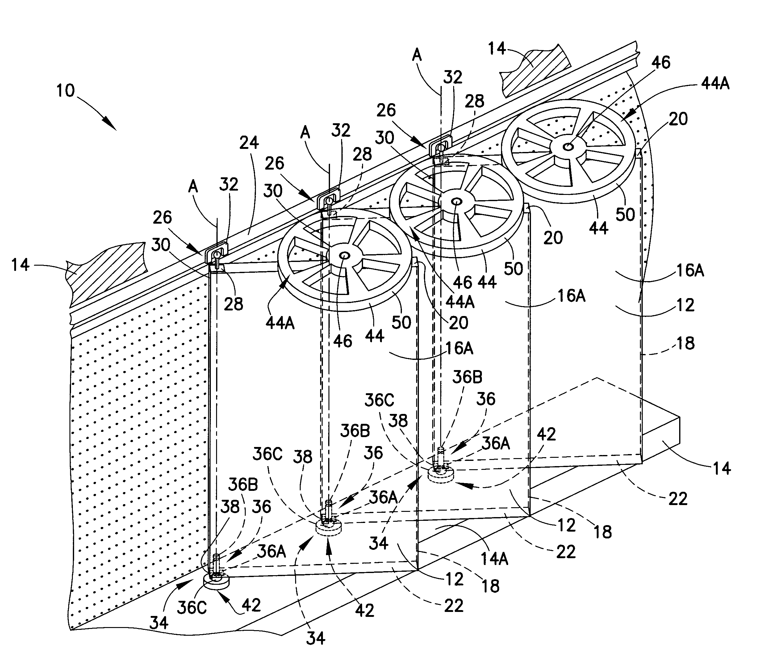
[0020]Referring to FIG. 1, a storage system 10 is shown having three panels 12 pivotally positioned on a mounting structure 14. Each of the panels 12 has two storage areas 16A, 16B secured to opposing faces of a frame 18. The storage areas 16A, 16B can include, for example, peg board, slot board, plywood, baskets, shelves, racks, pegs and / or hooks for storing and / or displaying products thereon. The frame 18 has a first edge 20 and a second edge 22 positioned on opposing ends thereof. The mounting structure 14 has a channel 24 secured thereto for adjustably positioning the panels 12 on the mounting structure. In one embodiment, the mounting structure 14 and the channel 24 are substantially parallel to one another.

[0021]As shown in FIG. 1, the storage system 10 includes three first pivot members 26 each having a frame portion 28 secured to a distal end 30 of the first edge 20 of respective panels 12. Each of the first pivot members 26 also have a first mounting portion 32 moveably po


PUM


Abstract

A storage system includes a mounting structure having one or more mounting pivot devices positioned thereon. The storage system also includes one or more frames defining a first edge and a second edge with frame pivot devices positioned coaxially therebetween. At least one of the frames has one or more storage receptacles disposed thereon. Each of the mounting pivot devices engages respective frame pivot devices such that the frames are movably positioned on the mounting structure. According to another aspect of the present invention, the storage system includes one or more delimiter wheels having an engagement surface located thereon. The delimiter wheels are rotatably positioned on the first and/or the second edges of a frame. The engagement surfaces of adjacent delimiter wheels movably and adjustably engage one another and space the frames apart from one another.

Description


Claims


Application Information

Patent Timeline
Owner HAFEY THOMAS V
Why Eureka
Try Eureka