Output DC offset protection for class d amplifiers

a technology of dc amplifiers and amplifiers, applied in the direction of amplifiers with modulator-demodulator, amplifier combinations, dc amplifiers with semiconductor devices/discharge tubes, etc., can solve the problems of large current to the speakers, fire risk, and disadvantage of technology, and achieve the effect of minimizing jitter

Inactive Publication Date: 2009-09-03
PANASONIC CORP +1
View PDF12 Cites 17 Cited by
  • Summary
  • Abstract
  • Description
  • Claims
  • Application Information

AI Technical Summary

Benefits of technology

The invention relates to an apparatus that detects pulses from light waves by measuring changes caused when they pass through them. This helps reduce any variations or errors introduced during this process.

Problems solved by technology

This patented describes an improved method for protecting electronic devices like loudspeakers during operation without damaging them caused by excessive electricity flow through their terminal connections (DC). One technical solution involves providing specific circuit designs aimed towards reducing unwanted voltages called residual currents. However, existing methods often result in errors where certain parts get too hot and could potentially lead to fires if they happen accidentally.

Method used


Image

  • Output DC offset protection for class d amplifiers
  • Output DC offset protection for class d amplifiers
  • Output DC offset protection for class d amplifiers

Examples


first embodiment

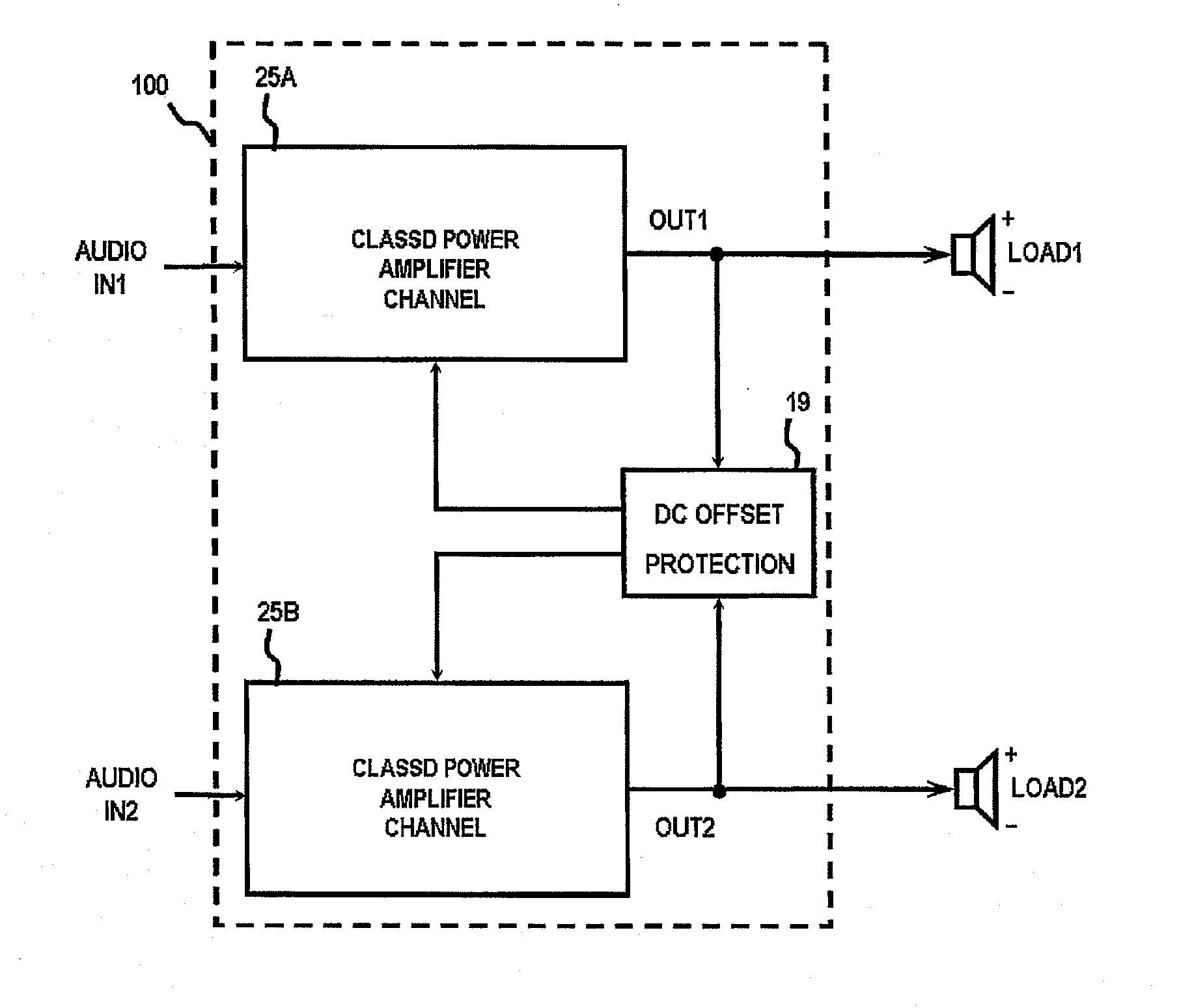
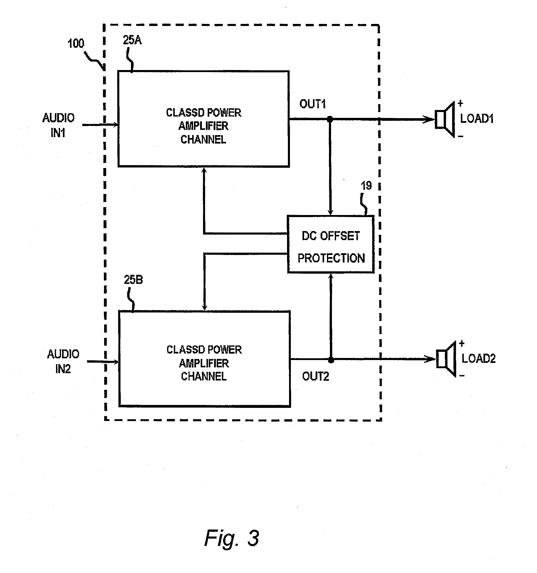
[0041]Referring to FIG. 3, a first embodiment of a class D power amplifier 100 according to the present invention is shown. In this example, system 100 is a two channel BTL class D amplifier that drives a speaker load. The Class D power amplifier 100 may be of any type, such types are, analog class D amplifier or a digital class D amplifier. Analog class D amplifier is an amplifier which receives analog signals as its input and goes to a process in which it is converted to a sequence of pulses whose averaged value is directly proportional to the signal's instantaneous amplitude. While on the other hand, digital class D amplifier is the one that receives pulses or digital signals as its input. Also, it is contemplated that these amplifiers can either use pulse width modulation, pulse density modulation (sometimes referred to as pulse frequency modulation) or more advanced form of modulation such as Delta-sigma modulation. In addition the amplifier 100 can also be a filterless class D am


PUM


Abstract

A class D amplifier with output DC offset protection is disclosed. The DC offset protection receives a PWM input signals from the outputs and investigates the PWM output signals whether there is a large DC voltage difference is being reflected on the speaker load. If so, shutdown signal SD will be sent by the DC offset protection to the PWM control logic and gate driver, thus, shutting down the output of the class D system and preventing disastrous condition from being develop across the speaker.

Description


Claims


Application Information

Patent Timeline
Owner PANASONIC CORP
Why Eureka
Try Eureka