Increased efficiency counter-rotating electric motor for propelling a boat

a counter-rotating, electric motor technology, applied in the direction of boat construction, marine propulsion, propulsive elements, etc., can solve the problems of high manufacturing cost, difficult fabrication, and difficult to manufacture, and achieve the effect of reducing the winding of weeds around the propeller, improving safety, and increasing the ability

Active Publication Date: 2010-01-07
E WISH TECH
View PDF12 Cites 10 Cited by
  • Summary
  • Abstract
  • Description
  • Claims
  • Application Information

AI Technical Summary

Benefits of technology

The technical effect of this patented design relates to improving security by reducing damage caused from boats operating near shaded areas or being pulled over due to grassy vegetation around them while also increasing efficiency when navigating underwater. Additionally, it simplifies the structure of the electric circuit used within the ship's motors and systems without adding extra components such as external slips ring terminals.

Problems solved by technology

Technological Problem: Current Electromagnetic Motion Compact Disc Motor Controllers (EMCC's) use an external frame where they can move around freely due to gravity. However, these devices cannot maintain their original position even if there were no impact on them caused by collisions between objects. Therefore, it becomes difficult to install EMC Cooler Centrops® (ECFC-1980)-type relays because they require long periods of time before being able to function properly. Another problem addressed by the inventions discussed in the technical problem solved through the patents involves improving the efficiency and durability of electronic power converters without increasing weight or cost over conventional designs.

Method used


Image

  • Increased efficiency counter-rotating electric motor for propelling a boat
  • Increased efficiency counter-rotating electric motor for propelling a boat
  • Increased efficiency counter-rotating electric motor for propelling a boat

Examples


Embodiment Construction

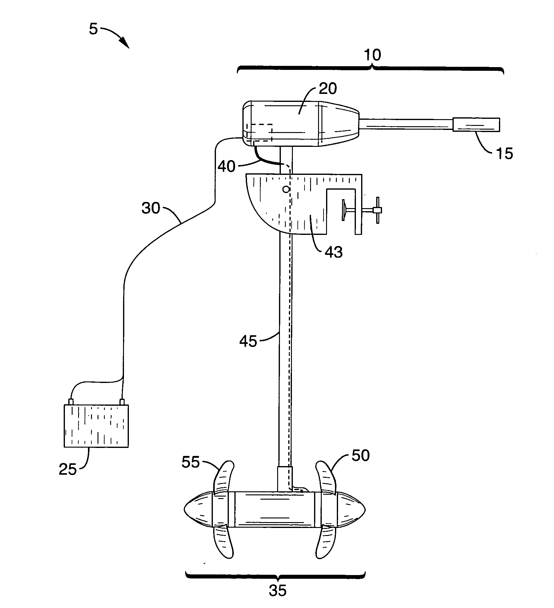
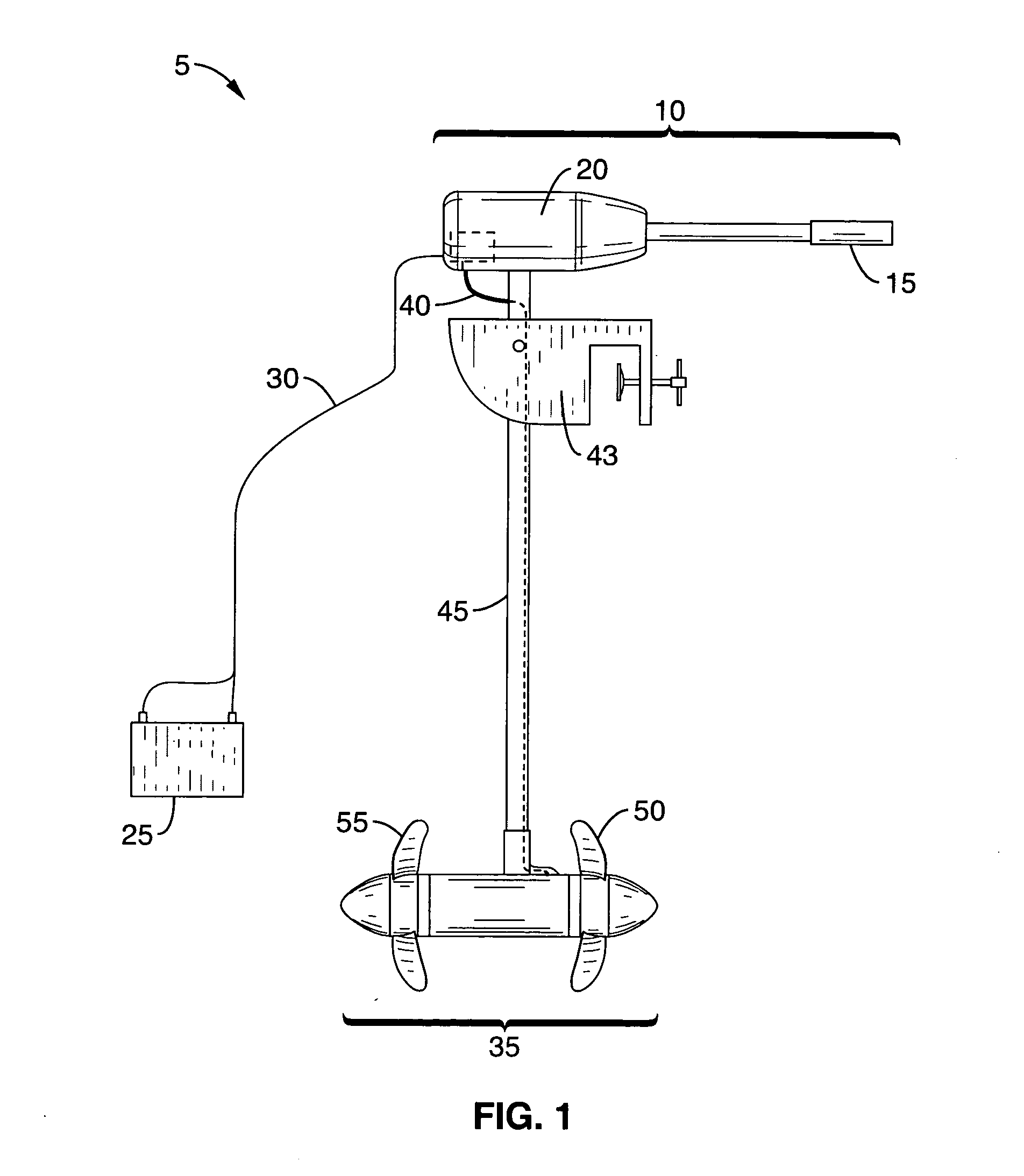
[0036]Referring more specifically to the drawings, for illustrative purposes the present invention is presented in the embodiments generally shown in FIG. 1 through FIG. 8. It will be appreciated that the subject apparatus may vary as to configuration and as to details of the parts without departing from the basic concepts as disclosed herein.

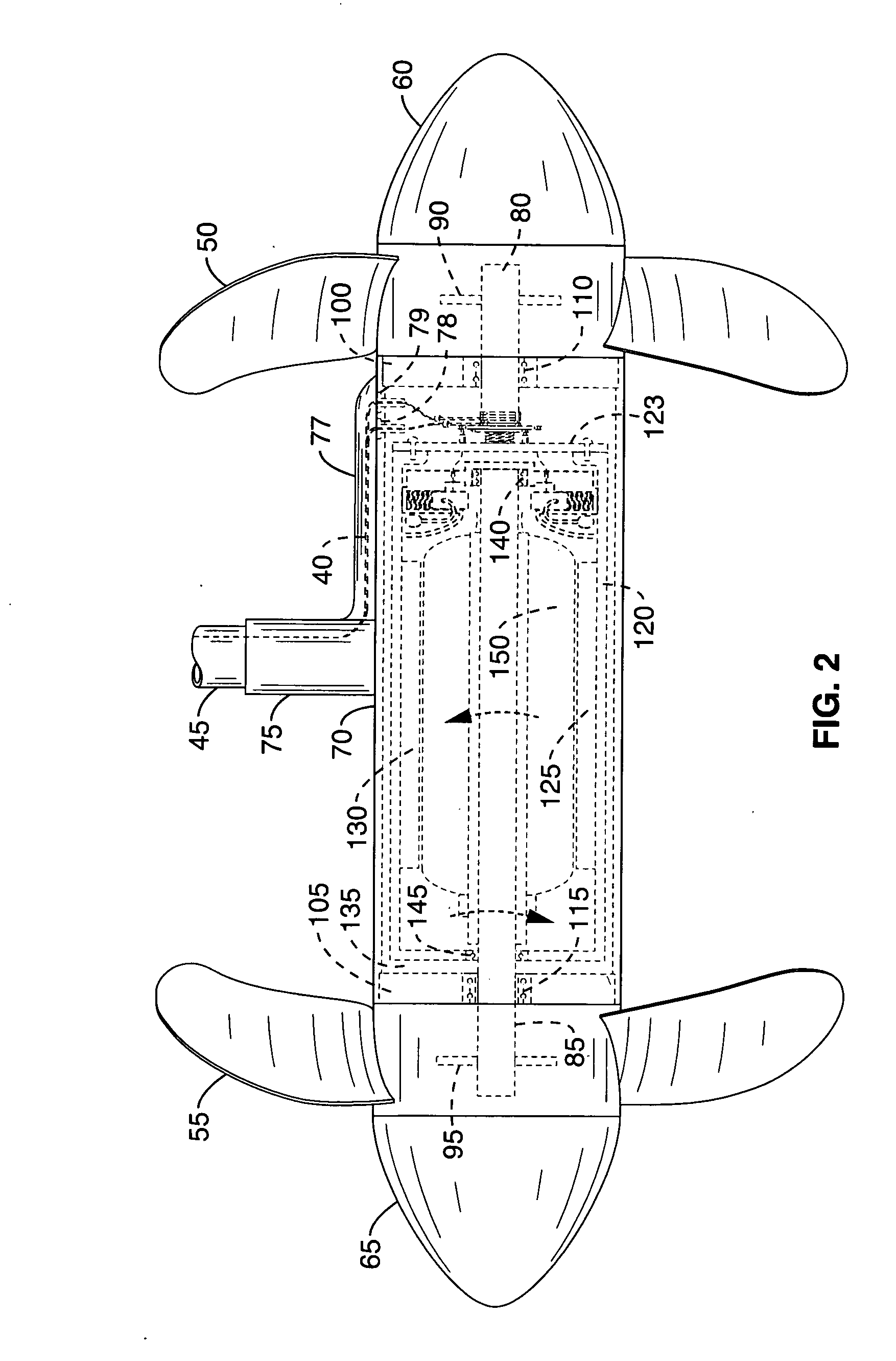
[0037]Generally, the subject invention is a counter-rotating electric motor and water-vehicle propulsion system utilizing the counter-rotating electric motor. The counter-rotating motor includes within a water-tight or secure motor housing a stator having first and second ends that rotates about a central axis in a first direction, an armature having first and second ends that rotates about the central axis in a second direction, wherein the stator surrounds at least a portion of the armature. A first axel is secured to the stator and extends along the central axis, wherein said first axel rotates in the first direction and a second axel is secure


PUM


Abstract

An enhanced counter-rotating electric motor and an associate propulsion system for use with a water-vehicle includes a motor housing, a stator within the housing that rotates about a central axis in one direction, an armature within the stator that rotates about the central axis in an opposite direction from the stator, a first axel that is secured to the stator and extends out from the housing, a second axel that is secured to the armature and extends out from the housing, water-tight rotational seals about each of the two axels, a centrifugal-force-balancing electrical connection mechanism that supplies functioning electrical communication between the motor and external electrical circuitry while operating the motor, and a propeller secured to each said axel.

Description


Claims


Application Information

Patent Timeline
Owner E WISH TECH
Why Eureka
Try Eureka