Optical member, display device using the optical member and movable body using the display device
a technology of optical member and display device, which is applied in the direction of picture reproducers using projection devices, instruments, television systems, etc., can solve the problem of bulky display device, and achieve the effect of suppressing the distortion of the background field of view
- Summary
- Abstract
- Description
- Claims
- Application Information
AI Technical Summary
Benefits of technology
Problems solved by technology
Method used
Image

Examples
first embodiment
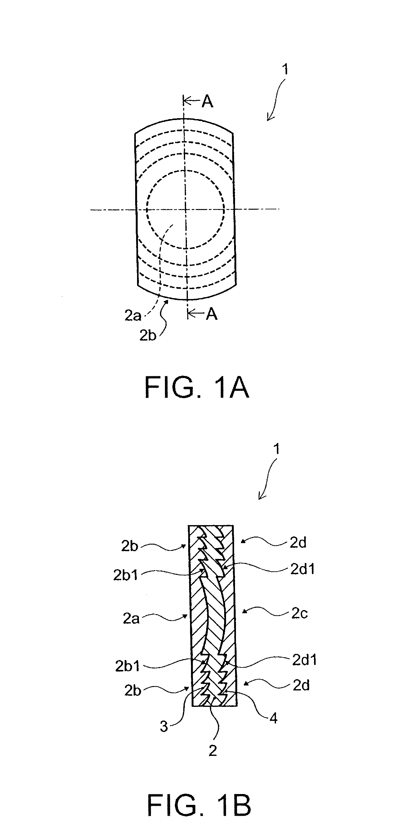
[0039]FIG. 1A and FIG. 1B are diagrams showing by way of example an optical member according to a FIG. 1A is a plan view of the optical member and FIG. 1B is a cross-sectional view along the line A-A in FIG. 1A.
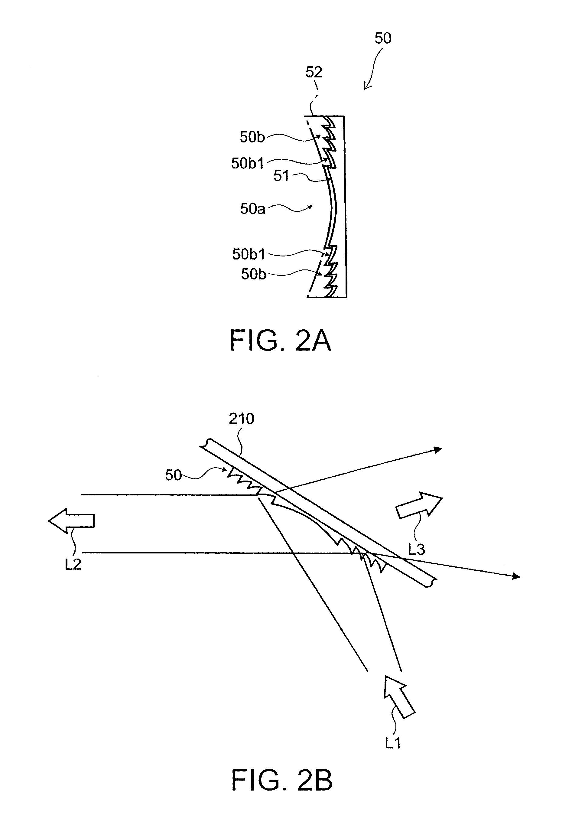
[0040]FIG. 2A and FIG. 2B are diagrams showing by way of example an optical member according to a comparative example. FIG. 2A is a cross-sectional diagram showing by way of example an optical member according to a comparative example and FIG. 2B is a cross-sectional diagram showing by way of example the action when the optical member according to the comparative example is provided on a projection plate.
[0041]First of all, an optical member according to a comparative example will be described.
[0042]As shown in FIG. 2A, a concave section 50a and a plurality of convex ridges 50b are provided on one of the main faces of an optical member 50 presenting a thin plate shape. The optical members 50 (concave section 50a and convex ridges 50b) are formed of transparent or semitransparen
second embodiment
[0074]FIG. 4A and FIG. 4B are diagrams illustrating by way of example an optical member according to a FIG. 4A is a plan view of the optical member and FIG. 4B is a cross-sectional view along the arrows B-B in FIG. 4A.
[0075]As shown in FIG. 4B, an optical layer 12, optical layer 13, and semi-transparent layer 14 are provided on an optical member 10 that presents a thin plate shape.
[0076]A concave section 12a and a plurality of convex ridges 12b are provided on one main face of an optical layer 12.
[0077]Also, as shown in FIG. 4A, a concave section 12a is provided in substantially the middle of the optical member 10. This concave section 12a presents a substantially circular shape in plan view. Also, convex ridges 12b are provided in concentric circular fashion around the concave section 12a. Also, a concave curved surface is provided on the main face of the concave section 12a and convex ridges 12b.
[0078]The concave section 12a presents a surface shape that is the same as the middle p
PUM
 Abstract
Description
Claims
Application Information
 - R&D Engineer
- R&D Manager
- IP Professional
- Industry Leading Data Capabilities
- Powerful AI technology
- Patent DNA Extraction
Browse by: Latest US Patents, China's latest patents, Technical Efficacy Thesaurus, Application Domain, Technology Topic.
© 2024 PatSnap. All rights reserved.Legal|Privacy policy|Modern Slavery Act Transparency Statement|Sitemap