Liquid discharge head and method of manufacturing the same
a liquid discharge head and manufacturing method technology, applied in the field of liquid discharge heads, can solve the problems of long time required, inability to manufacture a large number of inkjet recording heads, and inability to irradiate the area excluding the ink flow path hb>1601/b> as illustrated in fig. 10b, so as to reduce the damage to the ink flow path caused by the laser beam
- Summary
- Abstract
- Description
- Claims
- Application Information
AI Technical Summary
Benefits of technology
Problems solved by technology
Method used
Image

Examples
first embodiment
[0062]A first embodiment of the invention will be described with reference to the drawings.
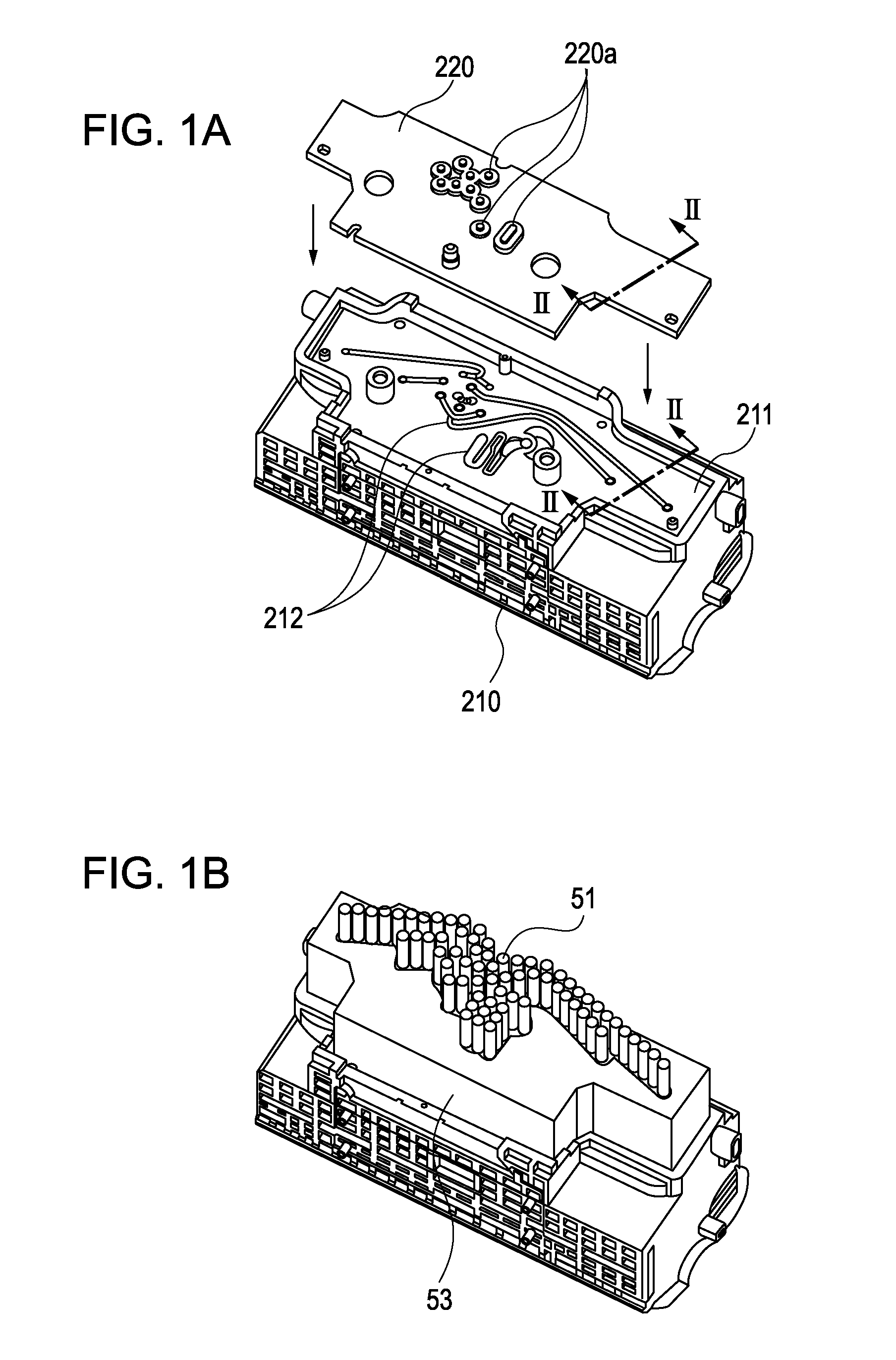
[0063]FIGS. 1A to 1C are perspective views illustrating, in the process of manufacturing a recording head, steps of attaching a flow path plate 220 to a tank holder 210 in which a flow path forming portion 211 is formed. An inclined surface formed in the flow path forming portion 211, which will be described below, is omitted from FIG. 1A.
[0064]FIG. 1A illustrates steps of preparing the flow path plate 220 and the flow path forming portion 211, which is integrally formed with the tank holder 210; and making the flow path plate 220 and the flow path forming portion 211 contact each other, at the periphery of an ink flow path to be welded, in such a manner that a flow path portion is disposed between the flow path plate 220 and the flow path forming portion 211.
[0065]FIG. 1B shows a step of holding the flow path plate 220 using a pressing jig 53, which is designed for use in laser irradiation, so t
second embodiment
[0084]Next, a second embodiment of the invention will be described.
[0085]Description of structures similar to those in the first embodiment is omitted and like numerals are used for corresponding portions. Descriptions of a method of laser welding and materials for a flow path forming portion and a flow path plate are omitted because they are similar to those in the first embodiment.
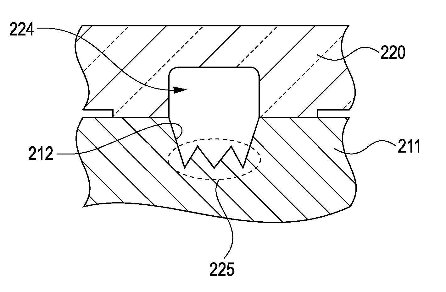
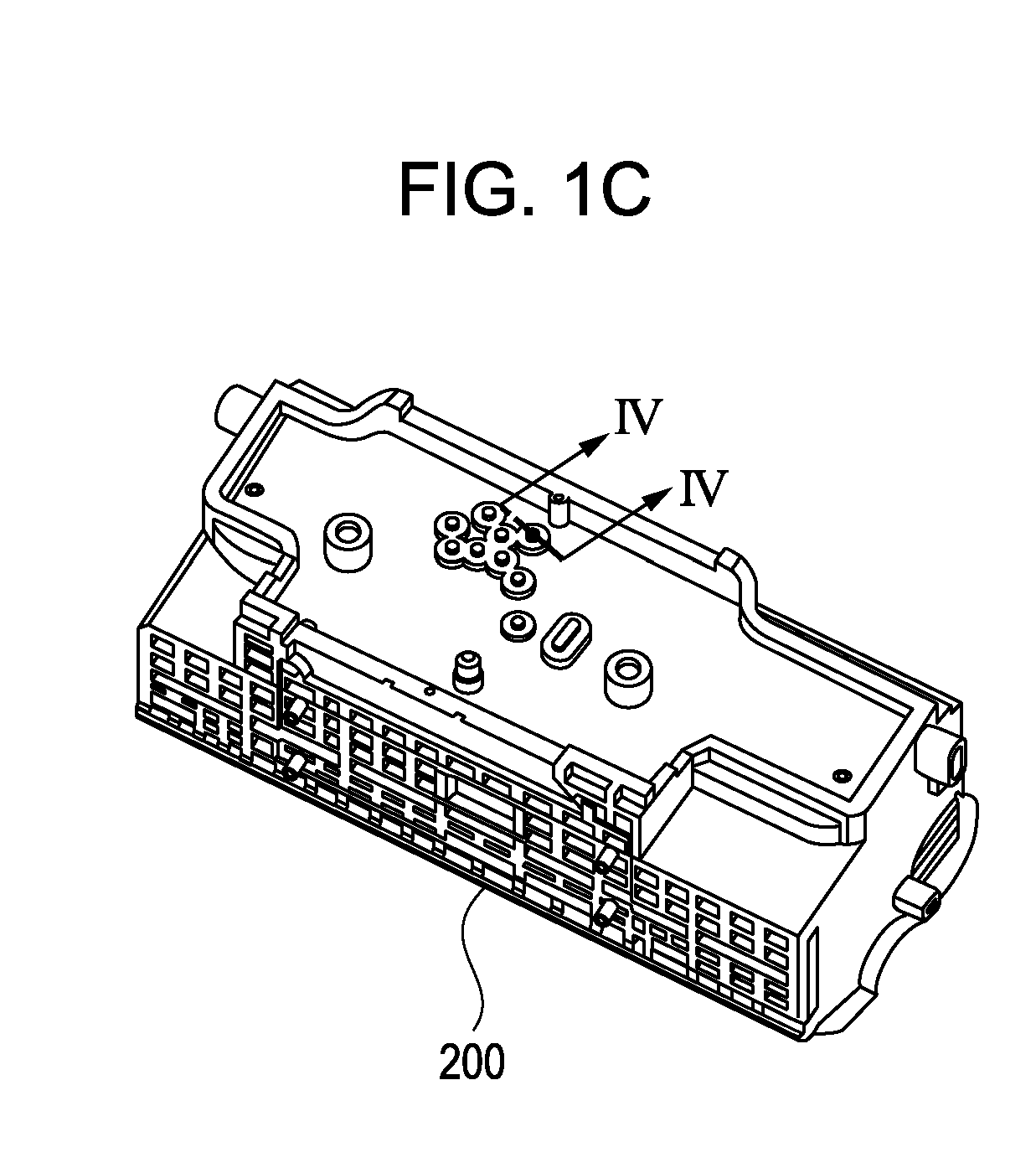
[0086]FIG. 4A is a sectional view taken along IV-IV of FIG. 1C illustrating the structure of the flow path portion. FIG. 4B is an explanatory view illustrating damage caused to the ink flow path when the structure of the embodiment is not adopted.
[0087]As illustrated in FIG. 4B, a damaged portion 620 may be formed in a flow path portion 212a of the ink flow path 224, when the flow path portion 212a is irradiated with a laser beam that has passed through an opening 220a formed in the flow path plate 220. Since the damaged portion 620 formed in the flow path portion 212a has been directly irradiated with the
third embodiment
[0092]Next, a third embodiment of the invention will be described.
[0093]Description of structures similar to those in the first and second embodiments is omitted and like numerals are used for corresponding portions. Descriptions of a method of laser welding and materials for a flow path forming portion and a flow path plate are omitted because they are similar to those in the first embodiment.
[0094]As illustrated in FIG. 5, in the embodiment, a flow path portion includes an inclined surface 226 and a surface that is substantially parallel to the direction of the laser beam. The inclined surface 226 of the flow path portion has a mirror finish. By providing a mirror finish to the inclined surface, the reflectance of the inclined surface can be increased. Thus, even if the inclined surface is inclined at a small angle with respect to the direction of the laser beam, that is, even if the angle of incidence of the laser beam with respect to the inclined surface is small, damage caused by
PUM
| Property | Measurement | Unit |
|---|---|---|
| Angle | aaaaa | aaaaa |
| Reflectance | aaaaa | aaaaa |
Abstract
Description
Claims
Application Information
 - R&D Engineer
- R&D Manager
- IP Professional
- Industry Leading Data Capabilities
- Powerful AI technology
- Patent DNA Extraction
Browse by: Latest US Patents, China's latest patents, Technical Efficacy Thesaurus, Application Domain, Technology Topic.
© 2024 PatSnap. All rights reserved.Legal|Privacy policy|Modern Slavery Act Transparency Statement|Sitemap