Fixing device and image forming apparatus
a technology of fixing device and fixing plate, which is applied in the direction of electrographic process apparatus, instruments, optics, etc., can solve the problems of ineffective reduction of sliding friction between the fixing belt, pressure pad, and low friction sheet b>64/b>, so as to prevent wrinkles, prevent damage to low friction sheet, and long-term stability of low friction sheet
- Summary
- Abstract
- Description
- Claims
- Application Information
AI Technical Summary
Benefits of technology
Problems solved by technology
Method used
Image

Examples
first embodiment
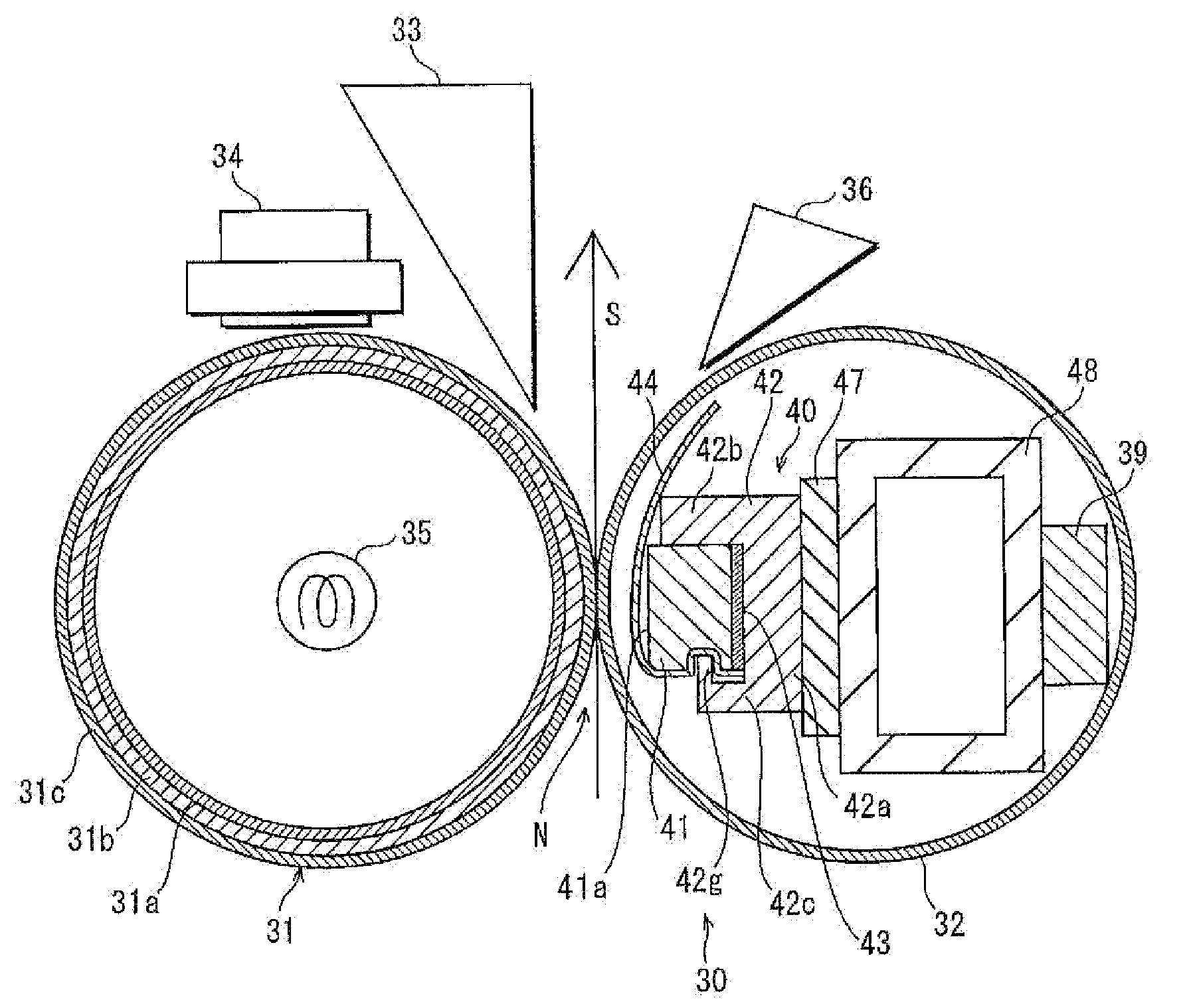
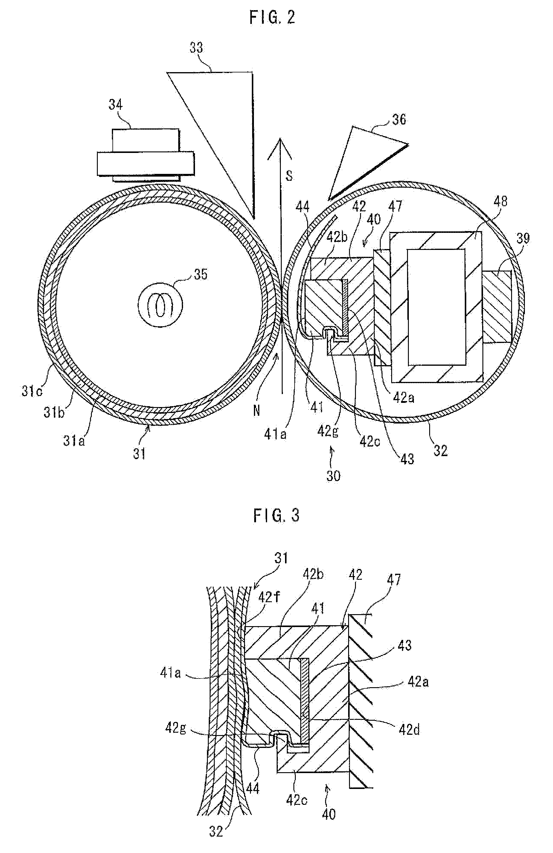
[0068]FIG. 4 is cross-sectional view of the main part of the pressing member 40. FIG. 5 is a perspective view of the main part of the pressing member 40. Note that each of FIGS. 4 and 5 is depicted such that the upper side of the sheet of the drawing is the side where the fixing roller 31 exists. Also, each depicts the pressing member 40 in the state of not pressing against the pressure belt 32. Thus, the low friction sheet 44 is depicted as though being away from the pressure belt 32.
[0069]The rigid pressing part 42 disposed on the elastic sheet 47 includes a main supporting structure 42a, a rigid presser 42b and a side wall 42c. The main supporting structure 42a extends straight along the width direction of the pressure belt 32. The rigid presser 42b is provided along the downstream lateral side of the main supporting structure 42a with respect to the rotation direction of the fixing roller 31. The side wall 42c is provided along the upstream lateral side of the main supporting struc
modification example 1
of Pressing Member
[0094]FIG. 6 is a cross-sectional view of the main part of another example of the pressing member 40 used in the fixing device pertaining to the embodiment of the present invention. In the pressing member 40 shown in FIG. 6, the full width of one end of the reinforcing part 43 with respect to the width direction of the pressure belt 31, which is closer to the side wall 42c of the rigid pressing part 42 than the other end, protrudes toward the side wall 42c, farther than the upstream lateral side 41b of the elastic pressing part 41. This protruding end is hereinafter referred to as a sheet holder 43a.
[0095]The side wall 42c of the rigid pressing part 42 covers the sheet holder 43a of the reinforcing part 43. The side wall 42c has a groove 42h that extends across the full width of the side wall 42c. The sheet holder 43a fits to the groove 42h. The cross section of the groove 42h is in the shape of a rectangular. The inside surface of the groove 42h is contiguous with t
modification example 2
of Pressing Member
[0100]In the pressing member 40 shown in FIG. 6, the upstream end 44a of the low friction sheet 44 may be, as shown in FIG. 7, extended toward the main supporting structure 42a, running over the groove 42h in the side wall 42c. If this is the case, a depression 42k may be provided in the supporting face 42d of the main supporting structure 42a across the full-width of the supporting face 42d with respect to the width direction of the pressure belt 32, such that the running-over part of the upstream end 44a fits into the groove 42h.
[0101]With such a structure, the upstream end 44a of the low friction sheet 44 follows the whole inside surface of the groove 42h provided in the side wall 42c, and is held by the whole inside surface of the groove 42h and the sheet holder 43a inserted into the groove 42h. Thus, a long portion of the upstream end 44a is held along the rotation direction of the pressure belt 32. This more surely prevents the upstream end 44a from slipping ou
PUM
 Abstract
Description
Claims
Application Information
 - R&D Engineer
- R&D Manager
- IP Professional
- Industry Leading Data Capabilities
- Powerful AI technology
- Patent DNA Extraction
Browse by: Latest US Patents, China's latest patents, Technical Efficacy Thesaurus, Application Domain, Technology Topic.
© 2024 PatSnap. All rights reserved.Legal|Privacy policy|Modern Slavery Act Transparency Statement|Sitemap