Relay module, electrical center having a relay module and method of assemblying the same

Active Publication Date: 2010-12-23
APTIV TECH LTD
View PDF15 Cites 5 Cited by
  • Summary
  • Abstract
  • Description
  • Claims
  • Application Information

AI Technical Summary

Problems solved by technology

However, this alternative usually requires mechanical assistance

Method used


Image

  • Relay module, electrical center having a relay module and method of assemblying the same
  • Relay module, electrical center having a relay module and method of assemblying the same
  • Relay module, electrical center having a relay module and method of assemblying the same

Examples


Embodiment Construction

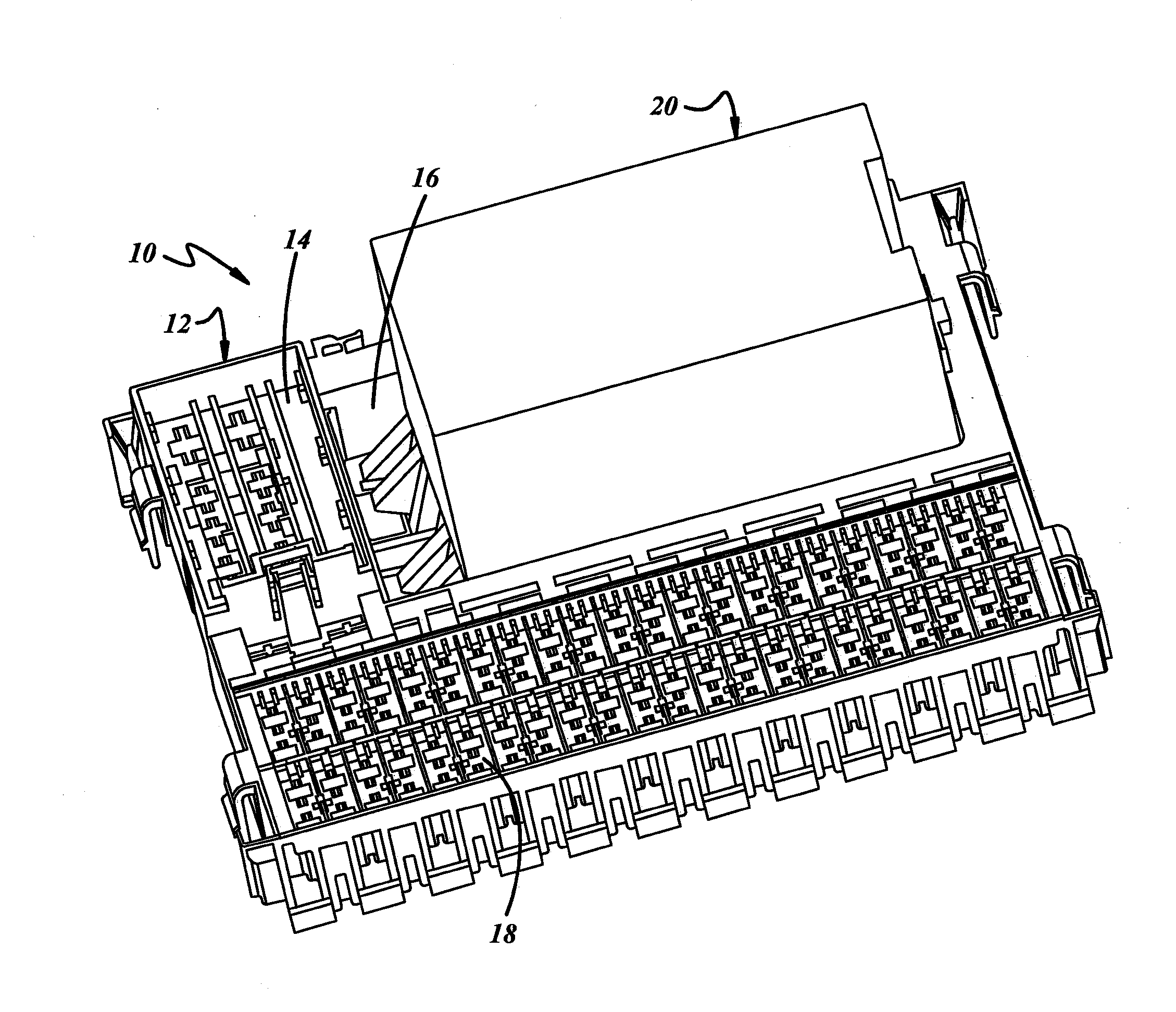
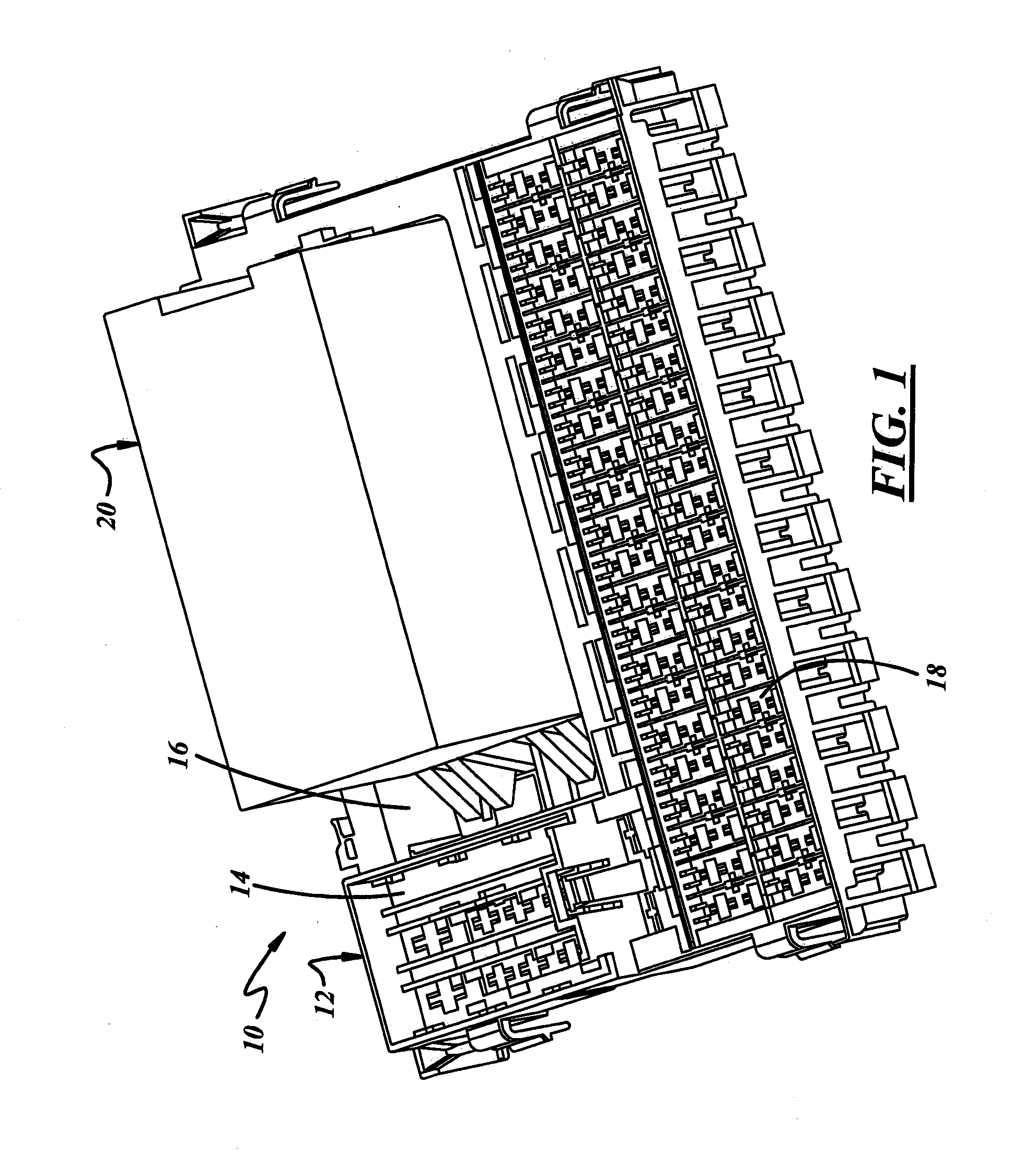
[0011]Referring now to the drawings, an electrical center illustrating an embodiment of the invention is indicated generally at 10. Electrical center 10 comprises a housing 12 that has differently configured areas 14, 16 and 18 for receiving various electrical components such as fuses, relays, etc. After being loaded with these various electrical components, housing 12 is then typically assembled into an automobile and connected into the electrical system of the automobile.

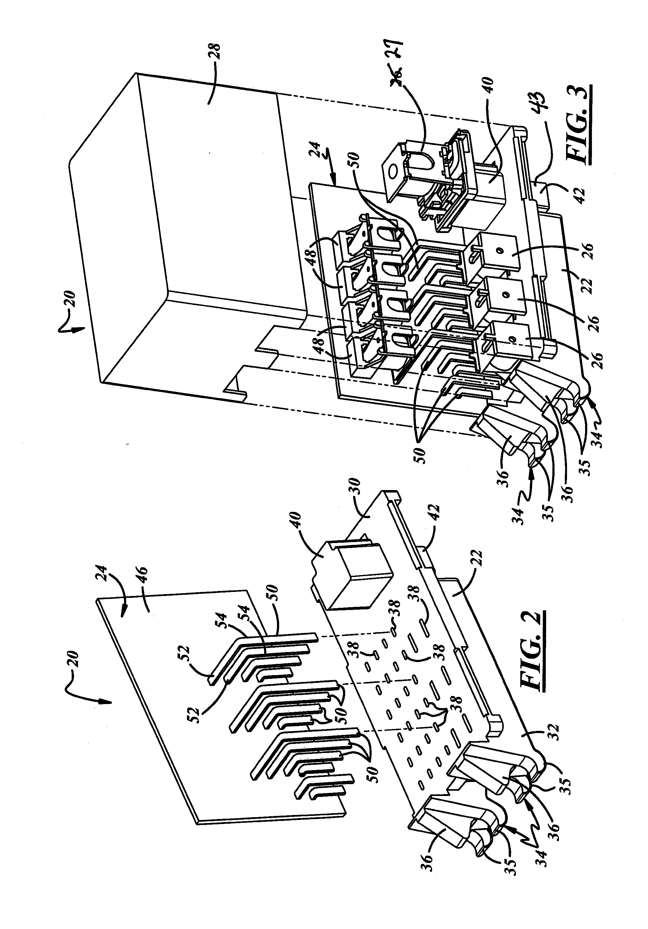
[0012]Electrical center 10 includes a relay module 20 that is plugged into area 16 that is specifically designed to receive the relay module. Relay module 20 comprises a lower base 22, a printed circuit board assembly 24, several plug in electronic components 26 and a cover 28 as best shown in FIGS. 2, 3 and 4.

[0013]Lower base 22 which is preferably of one piece molded plastic construction comprises a tray 30 having a depending shroud 32 at one end portion. A pair of laterally spaced couplers 34 are integrally attach


PUM

PropertyMeasurementUnit
Angleaaaaaaaaaa
Flexibilityaaaaaaaaaa
Areaaaaaaaaaaa

Abstract

An electrical center includes a housing and a relay module that is disposed in a well of the housing. The relay module has a lower base, a printed circuit board assembly, plug in electronic components and a cover. The lower base includes a tray having a depending shroud at one end portion and a pair of laterally spaced couplers that are integrally attached to an end wall of the tray. The end portion of the tray that has the depending shroud has a plurality of apertures that extend through the end portion of the tray for receiving terminal portions that extend through the apertures. An opposite end portion of the tray has an upper pedestal that is part of a connector body that extends through the tray to a lower socket. The printed circuit board assembly has a printed circuit board that is attached to the top of the tray near a side edge, a plurality of relays that are attached to an upper portion of the printed circuit board. The relays are electrically connected to a plurality of terminals that are disposed beneath the relays. These terminals have portions that plug into the apertures and terminate in free ends disposed inside the shroud. The relay module also includes plug in electronic components that are plugged into the end portion of tray so that their metal terminal tabs extend through the apertures and into the space inside the shroud. The relay module also includes a main relay that is mounted on the pedestal for electrical connection to a wiring harness that plugs into the lower socket of the connector body. The relay module is retained in the well of the housing by an internal lock bar that engages the couplers at one end and an internal lock nib that engages a flexible lock arm of the relay module the other end.

Description


Claims


Application Information

Patent Timeline
Owner APTIV TECH LTD
Why Eureka
Try Eureka