Stack structure of printed circuit boards using interposer and electronic device including the same

a printed circuit board and interposer technology, applied in the direction of fixed connections, electrical apparatus casings/cabinets/drawers, display/control units, etc., can solve the problems of electronic device malfunction, printed circuit board may be displaced relative to the other printed circuit board, and assembly having a significant height, etc., to achieve high configuration

Active Publication Date: 2020-08-20
SAMSUNG ELECTRONICS CO LTD
View PDF0 Cites 4 Cited by
  • Summary
  • Abstract
  • Description
  • Claims
  • Application Information

AI Technical Summary

Benefits of technology

The technical effect that this technology allows for better protection against damage caused when there are sudden movements between different layers during assembly or use on electronic devices due to their large number of connections made through wires attached to them.

Problems solved by technology

The technical problem addressed by this patented technology relates to reducing the size of electronics while still ensuring that they can connect properly when subjected to shock or other physical damage during use without losing their functionality.

Method used


Image

  • Stack structure of printed circuit boards using interposer and electronic device including the same
  • Stack structure of printed circuit boards using interposer and electronic device including the same
  • Stack structure of printed circuit boards using interposer and electronic device including the same

Examples


Embodiment Construction

[0023]FIGS. 1 through 9C, discussed below, and the certain embodiments used to describe the principles of the present disclosure in this patent document are by way of illustration only and should not be construed in any way to limit the disclosure. Those skilled in the art will understand that the principles of the present disclosure may be implemented in any suitably arranged system or device.

[0024]Hereinafter, embodiments of the present disclosure are described in detail with reference to accompanying drawings.

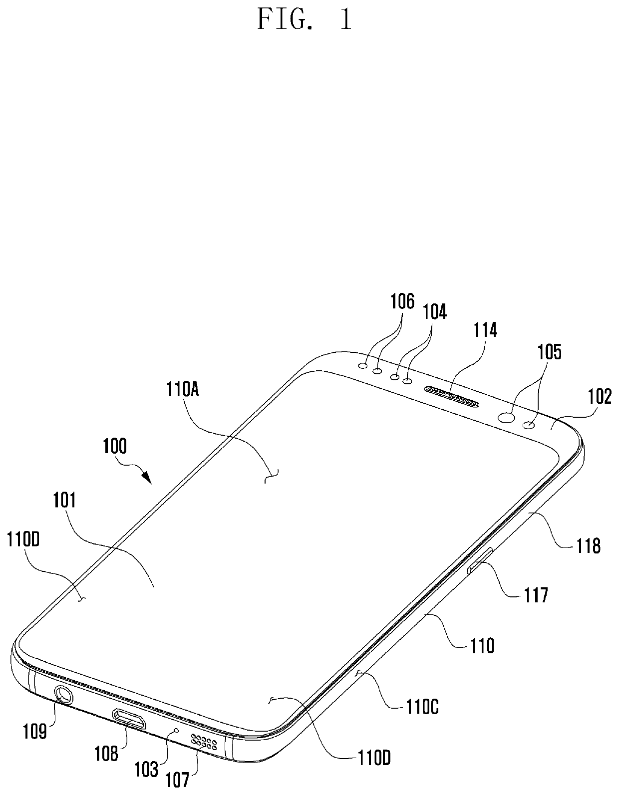
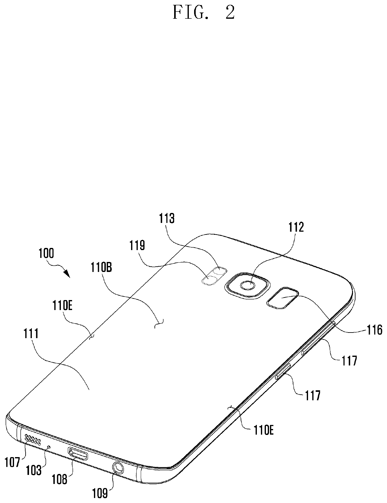
[0025]FIG. 1 illustrates a perspective view showing a front surface of a mobile electronic device 100 according to an embodiment, and FIG. 2 illustrates a perspective view showing a rear surface of the mobile electronic device 100 shown in FIG. 1.

[0026]Referring to FIGS. 1 and 2, the mobile electronic device 100 may include a housing 110 that includes a first surface (or front surface) 110A, a second surface (or rear surface) 110B, and a lateral surface 110C that surrounds a sp


PUM


Abstract

An electronic device is disclosed, including: a first support member including at least one screw-fastening portion; a first printed circuit board (PCB) stacked on the first support member and including at least one screw-fixing portion facing the at least one screw-fastening portion; a second PCB spaced apart from the first PCB, including a first screw guide groove; an interposer disposed between the first PCB and the second PCB electrically connecting them and including a second screw guide groove facing the first screw guide groove; and a second support member stacked on the second PCB and including a screw inlet portion facing the first screw guide groove. The second support member, the first PCB, and the first support member are fixed to each other via a screw inserted through the screw inlet portion.

Description


Claims


Application Information

Patent Timeline
Owner SAMSUNG ELECTRONICS CO LTD
Why Eureka
Try Eureka