Driving device and image forming apparatus

a technology of driving device and image forming apparatus, which is applied in the direction of gearing, hoisting equipment, instruments, etc., can solve the problems of large degree of image degradation, non-uniformity of above-described rotational speed, image expansion and contraction, etc., and achieve the effect of eliminating an image of eccentricity and high accuracy

Inactive Publication Date: 2011-01-27
CANON KK
View PDF3 Cites 9 Cited by
  • Summary
  • Abstract
  • Description
  • Claims
  • Application Information

AI Technical Summary

Benefits of technology

The technical effect that this patented technology solves are improved precision during rotation caused by controlling the amount at which it's shaft turns faster or slower without causing any issues like unevenness between different parts on its drive train due to misalignment from other components such as bearings.

Problems solved by technology

The technical problem addressed in this patents is how to reduce variations in the rotating speeds caused by differences in geometry between components involved in the process while maintaining accurate control over the movement of the photoreceptor drum. This requires precise measurements and compensations based upon factors other than those mentioned earlier without affecting any changes made about them.

Method used


Image

  • Driving device and image forming apparatus
  • Driving device and image forming apparatus
  • Driving device and image forming apparatus

Examples


first embodiment

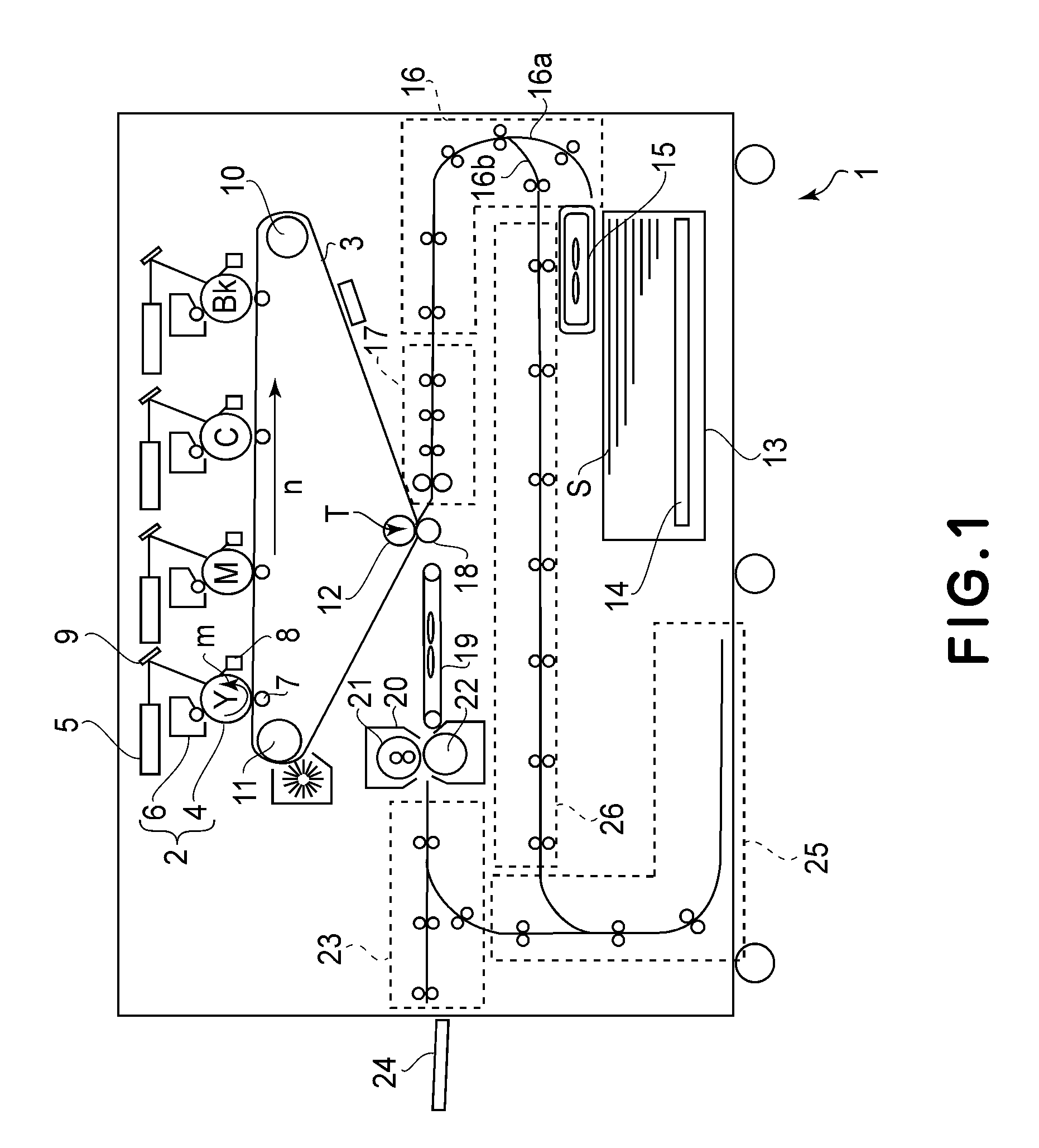
[0030]First Embodiment of the present invention will be described with reference to FIGS. 1 to 8. First, an image forming apparatus in this embodiment will be described with reference to FIG. 1. Incidentally, as the image forming apparatus to which the present invention is applicable, in addition to an electrophotographic image forming apparatus, those of a plurality of types including, e.g., an offset print type, an ink jet type, and the like. Of these types, an image forming apparatus 1 shown in FIG. 1 is a color image forming apparatus of the electrophotographic type. Further, the image forming apparatus 1 is a so-called intermediary transfer and tandem type image forming apparatus in which image forming portions 2 for four colors of yellow (Y), magenta (M), cyan (C) and black (Bk) are disposed side by side on an intermediary transfer belt 3 as an image bearing member. Such an image forming apparatus has gone mainstream in recent years from the viewpoint of excellence in thick paper

second embodiment

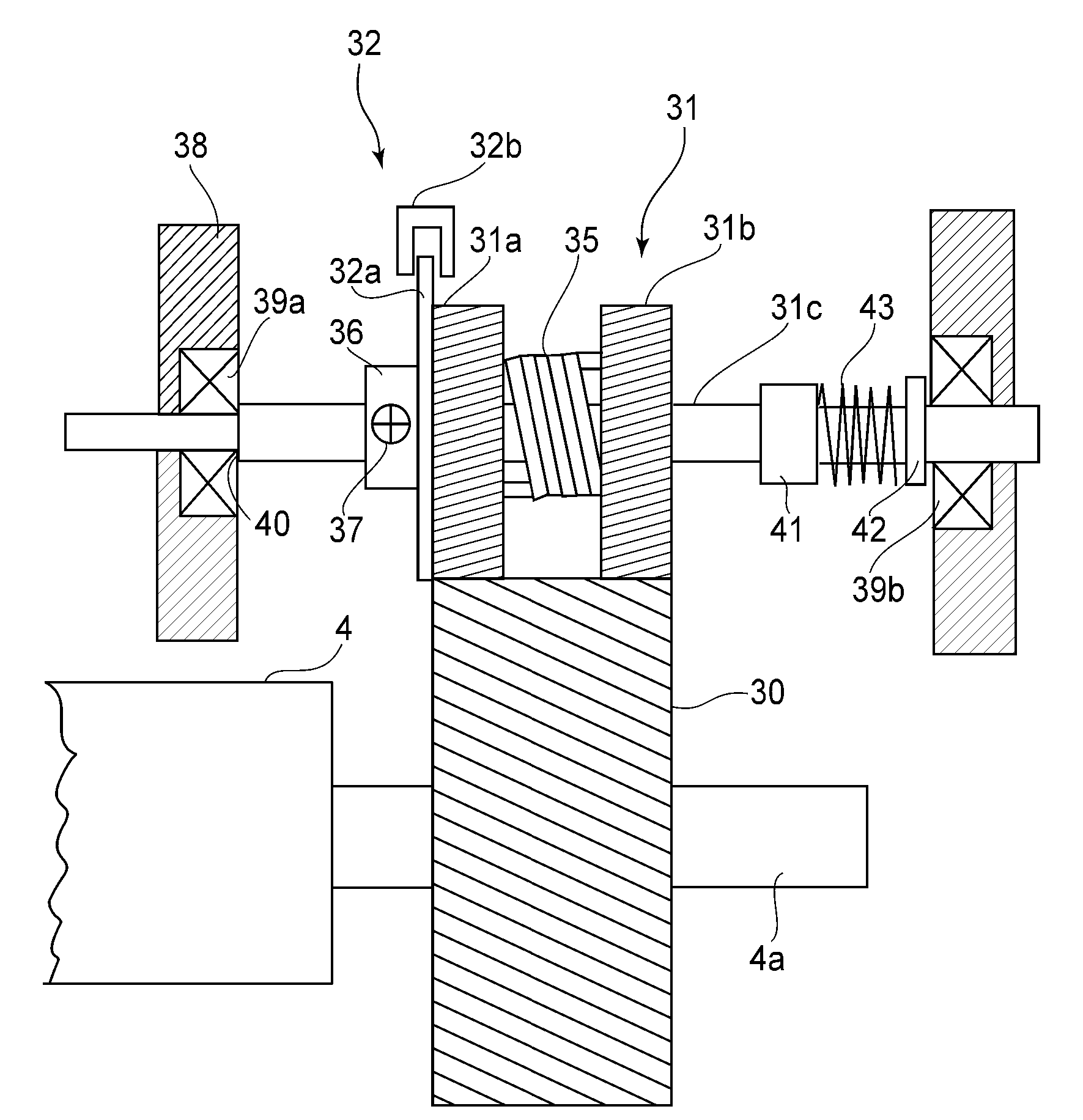
[0062]Second Embodiment of the present invention will be described with reference to FIGS. 10, 11, 12(a) and 12(b). In this embodiment, a flywheel 44 which is an inertial member is fixed on the rotation shaft 31c of the follower gear 31. Other constitutions and functions are similar to those in the above-described First Embodiment, thus being omitted from detailed description. Generally, it has been known that an inertial effect of the inertial member having the same weight and the same radius is achieved as the square of the rotational speed ratio. For this reason, by mounting the flywheel 44 on the follower gear 31 rotating at the speed higher than that of the photosensitive member gear 30 as in this embodiment, a sufficient inertial effect can be obtained even when the flywheel 44 has a small diameter.

[0063]Further, in this embodiment, by using the follower gear 31 as the scissors gear to sandwich the photosensitive member gear 30, rigidity of the engaging portion between the follow


PUM


Abstract

A drive device includes a drive source; a rotatable member gear, fixed on a rotation shaft of a rotatable member, for being rotated by transmitting thereto a driving force from the driving source; a follower gear, including a pair of gears which are coaxially disposed with each other and are rotatable at the same rotational speed by rotation of the rotatable member gear and including an urging device for urging the pair of gears in rotational directions opposite from each other, for being rotated at the rotational speed higher than that of the rotatable member gear; a rotation detecting device, including a single flag rotatable together with the follower gear and including a detecting portion for detecting passing of the flag, for detecting rotation of the follower gear; a computing portion for computing rotation fluctuation of the rotatable member gear from a signal of the detecting portion; a storing portion for storing a computation result of the computing portion; and a driving source control portion for controlling said driving source on the basis of the computation result stored in the storing portion.

Description


Claims


Application Information

Patent Timeline
Owner CANON KK
Why Eureka
Try Eureka