Multi-carrier amplifier linearization system and method

a linearization system and amplifier technology, applied in the direction of transmission, line-faulst/interference reduction, transmitter/receiver shaping network, etc., can solve the problems of linearization of a pa, non-linear distortion of the output wireless signal, undesirable nonlinear distortion of the signal, etc., to achieve the effect of increasing the sdr

Inactive Publication Date: 2011-03-17
HER MAJESTY THE QUEEN & RIGHT OF CANADA REPRESENTED BY THE MIN OF IND THROUGH THE COMM RES CENT
View PDF14 Cites 72 Cited by
  • Summary
  • Abstract
  • Description
  • Claims
  • Application Information

AI Technical Summary

Benefits of technology

This patented describes methods used during electronic communication systems that can correct errors caused by imperfections such as harmonics interference signals. These techniques involve measuring changes made over time when transmitting analog audio data from multiple sources together without affecting their quality level negligibly. By comparing these measurements against predetermined values stored within memory, it becomes possible to estimate how well each source works before sending them downstream. Additionally, this technique involves analyzing spectral characteristics of the received speech waveform to determine if any deviations are due to specific factors like AM tone modulation or noise. Based on these estimates, control algorithms may be applied to generate new ones called pre-compensated corrections. Overall, this technology helps improve overall performance and efficiency of wireless communication networks.

Problems solved by technology

The technical problem addressed in this patents relates to improving the performance of communications equipment used over long distances without causing any unwanted effects like interference from other devices transmitting data wirelessly through different frequencies simultaneously. This requires accurate measurements of the non-ideal properties of transmission components called carrier waves due to their interaction between these harmonics. Current methods are limited because there may only work well for certain types of waveforms while others become more complex. Therefore, an objective of the current solution involves developing a new technique to accurately measure the nonvolatile nature of various aspects of the waveform's behavior during its propagation across the system.

Method used


Image

  • Multi-carrier amplifier linearization system and method
  • Multi-carrier amplifier linearization system and method
  • Multi-carrier amplifier linearization system and method

Examples


Embodiment Construction

[0033]In the following detailed description, numerous specific details are set forth in order to provide a thorough understanding of the invention. However it will be understood by those of ordinary skill in the art that the present invention may be practiced without these specific details. In other instances, well-known methods, procedures, components and circuits have not been described in detail so as not to obscure the present invention.

[0034]Some portions of the detailed description, which follow, arc presented in terms of algorithms and symbolic representations of operations on data bits or binary digital signals within a computer memory. These algorithmic descriptions and representations may be the techniques used by those skilled in the data processing arts to convey the substance of their work to others skilled in the art.

[0035]Unless specifically stated otherwise, as apparent from the following discussions, it is appreciated that throughout the specification discussions utili


PUM


Abstract

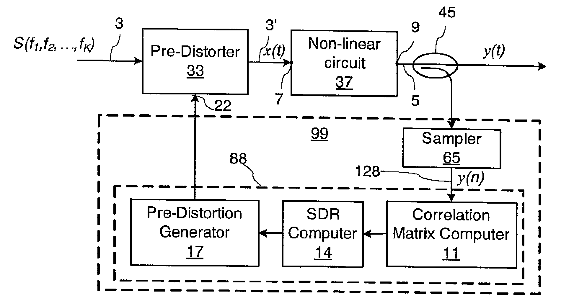
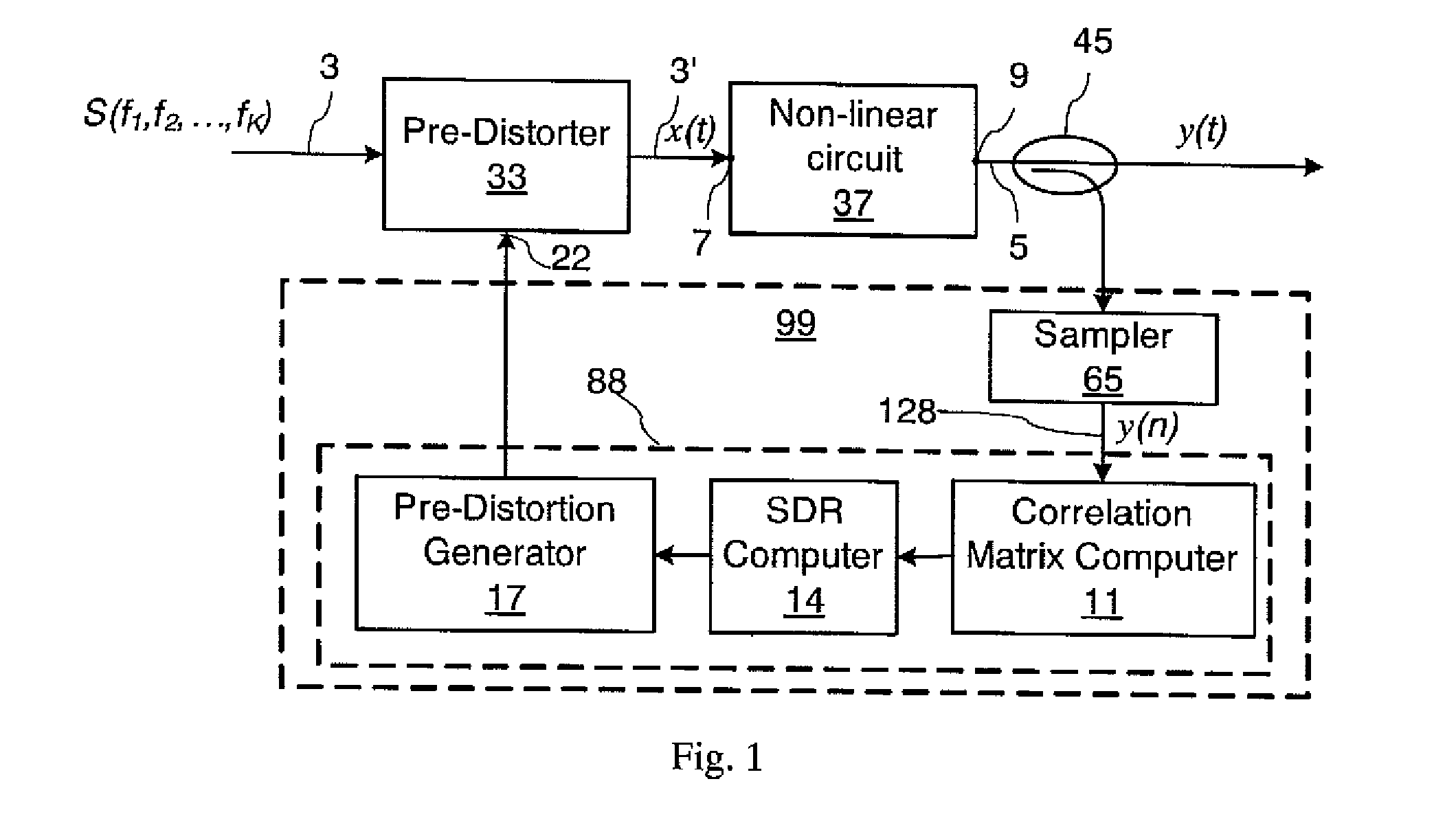
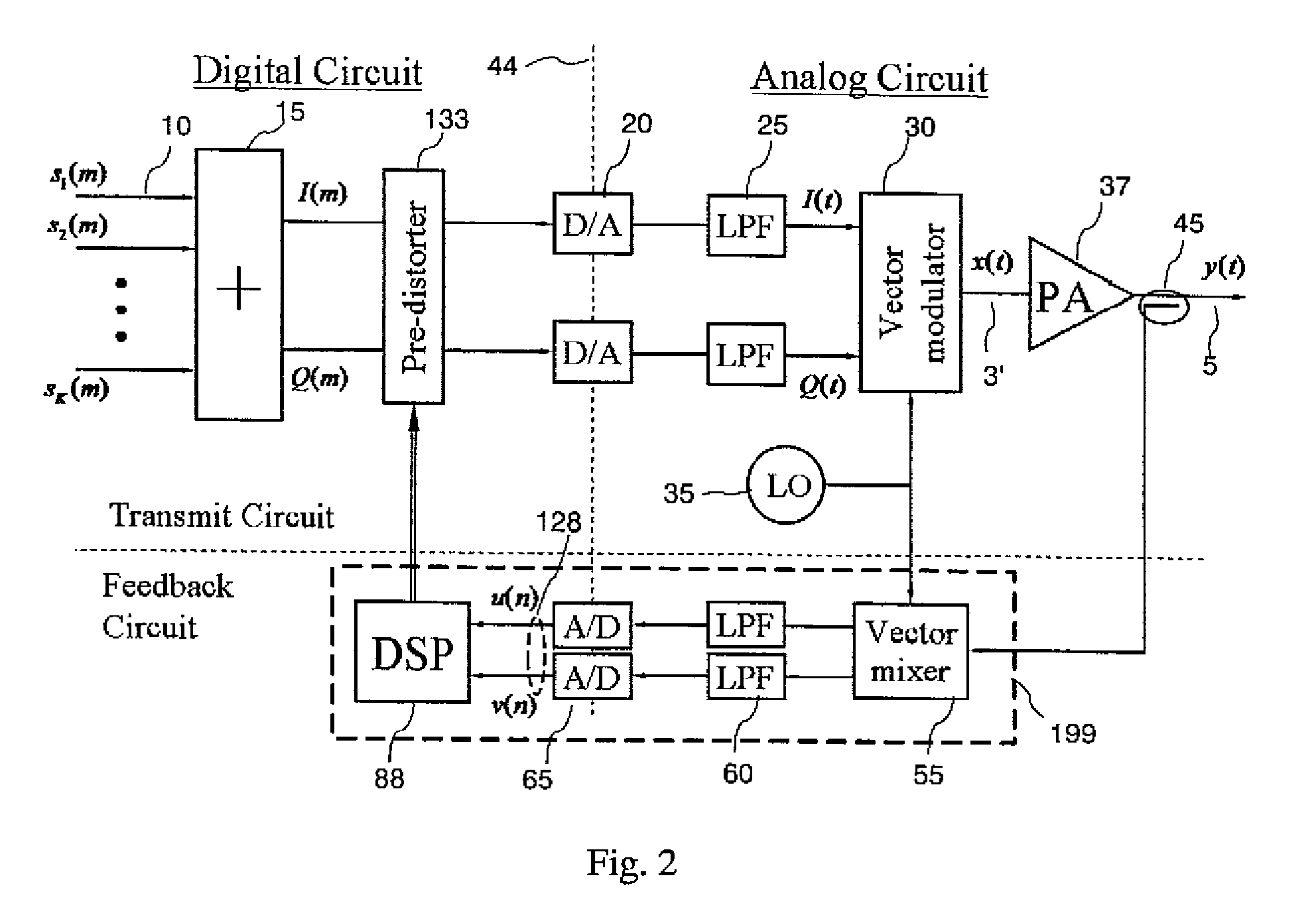
The invention relates to a method and circuit for linearizing amplifiers and other nonlinear circuits for multi-carrier signals. An output signal from the amplifier is sampled, and a correlation matrix of size N×N is computed from the sampled signal, wherein N exceeds the number of multiplexed carriers in the signal. A signal-to-distortion ratio (SDR) is then estimated based on a ratio of one or more largest to one or more smallest eigenvalues of the correlation matrix, and the signal into the amplifier is pre-distorted so as to maximize the SDR.

Description


Claims


Application Information

Patent Timeline
Owner HER MAJESTY THE QUEEN & RIGHT OF CANADA REPRESENTED BY THE MIN OF IND THROUGH THE COMM RES CENT
Why Eureka
Try Eureka