Mounting apparatus and mounting method

Active Publication Date: 2011-07-21
OLYMPUS CORP
View PDF38 Cites 10 Cited by
  • Summary
  • Abstract
  • Description
  • Claims
  • Application Information

AI Technical Summary

Benefits of technology

[0007]A mounting apparatus according to an aspect of the present invention includes a substrate; an optical component having a first surface on which light from the substrate is incident and a second surface from which the incident light goes out after the incident light is refracted; an adjustment unit that adjusts a position of the substrate and a position of the optical component by moving the substrate and the optical component relatively

Problems solved by technology

However, in some cases, when such an optical component is mounted on a substrate, one surface of the optical component opposite to another surface facing

Method used


Image

  • Mounting apparatus and mounting method
  • Mounting apparatus and mounting method
  • Mounting apparatus and mounting method

Examples


first embodiment

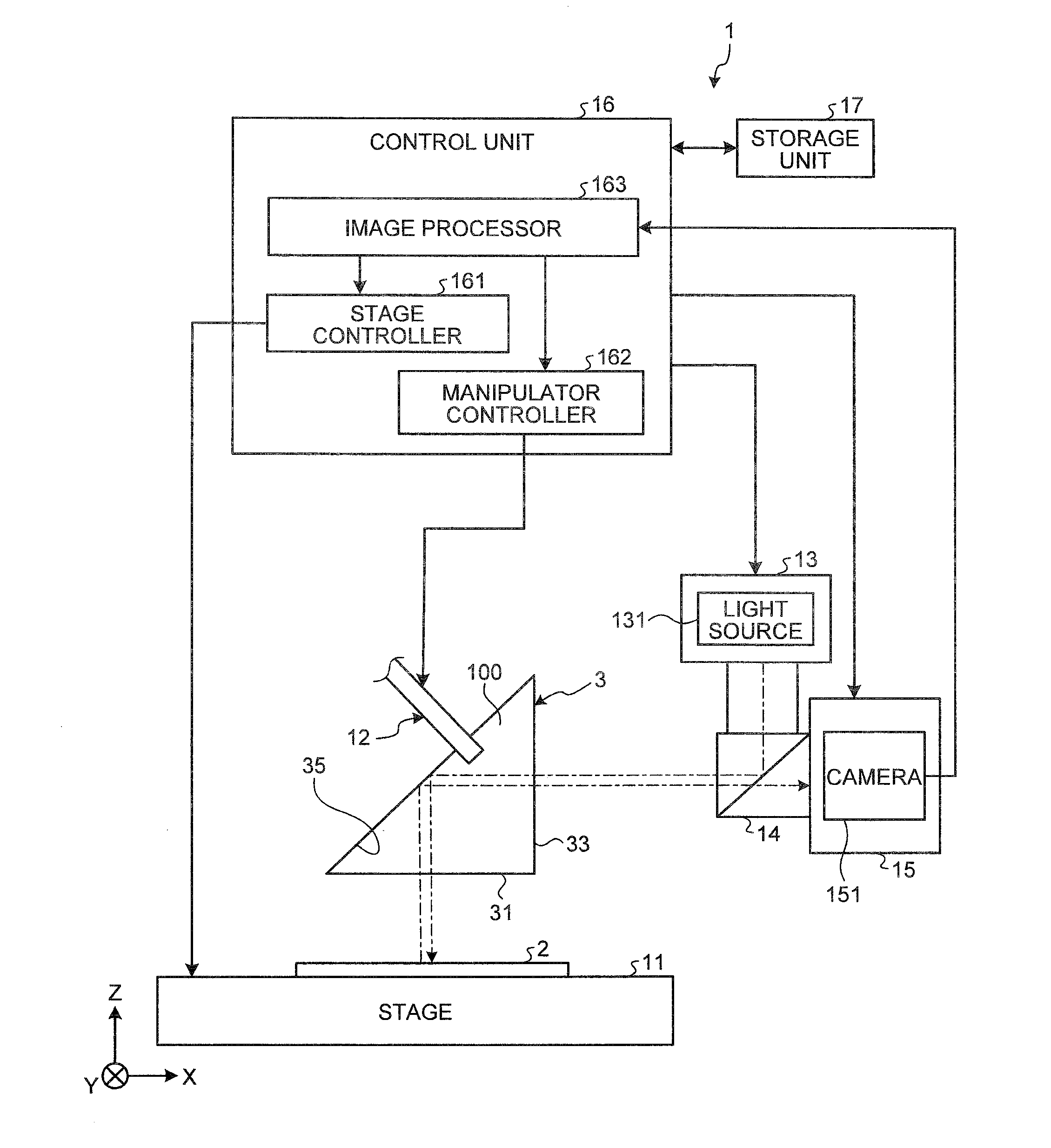
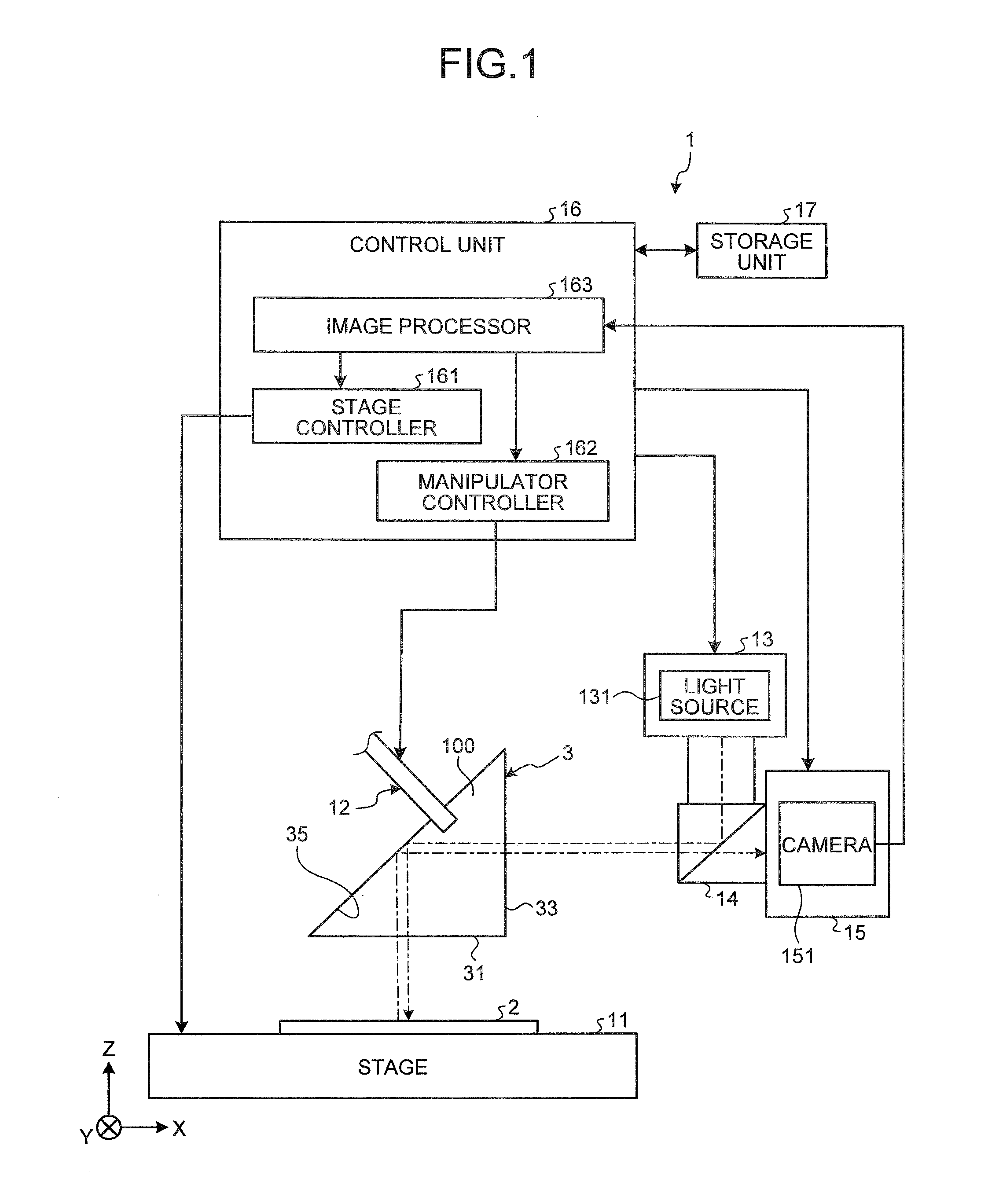
[0023]In a first embodiment of the present invention, a prism is illustrated as an optical component that refracts incident light and then sends out the incident light. A mounting apparatus that mounts the prism on a substrate that is provided with an alignment mark is illustrated as well. FIG. 1 is a schematic diagram illustrating an overall configuration of a mounting apparatus 1 according to the first embodiment. As depicted in FIG. 1, the mounting apparatus 1 includes a stage 11 on which a substrate 2 is mounted; a manipulator 12 that transfers a prism 3, an example of an optical component, that is mounted on the substrate 2; a light source unit 13; an optical path splitter 14; and an imaging unit 15.

[0024]The prism 3 that is held by the manipulator 12 is mounted on the substrate 2 later. Light from the side of the substrate 2 is incident on the prism 3. The prism 3 includes a first surface (hereinafter, “light going-out surface”) 31 that serves as a surface from which light incide

second embodiment

[0056]FIG. 10 is a schematic diagram illustrating an overall configuration of a mounting apparatus 1b of a second embodiment of the present invention. Parts like those of the first embodiment are denoted by like reference numerals. As illustrated in FIG. 10, the mounting apparatus 1b includes a light source unit 13-2 including a light source 131-2, an optical path splitter 14-2, and an imaging unit 15-2 including a camera 151-2, which are arranged above the stage 11, in addition to the light source unit 13, the optical path splitter 14, and the imaging unit 15 for capturing an image of the light incident surface 33 of the prism 3. The optical unit 13-2, the optical path splitter 14-2, and the imaging unit 15-2 can be realized using a configuration like that of the light source unit 13, the optical path splitter 14, and the imaging unit 15.

[0057]The optical unit 13-2, the optical path splitter 14-2, and the imaging unit 15-2 are used for capturing an image of the prism 3 from the side o


PUM

PropertyMeasurementUnit
Areaaaaaaaaaaa
Optical propertiesaaaaaaaaaa

Abstract

A mounting apparatus includes a substrate; an optical component having a first surface on which light from the substrate is incident and a second surface from which the incident light goes out after the incident light is refracted; an adjustment unit that adjusts a position of the substrate and a position of the optical component by moving the substrate and the optical component relatively with the first surface of the optical component and the substrate being opposed to each other; an imaging unit that is arranged in an optical path of the light that goes out from the second surface; and a control unit that controls an amount by which the adjustment unit moves the substrate and the optical component relatively according to image data which is captured by the imaging unit, and that mounts the optical component on the substrate.

Description


Claims


Application Information

Patent Timeline
Owner OLYMPUS CORP
Why Eureka
Try Eureka