Bottle cap with lock

Inactive Publication Date: 2011-10-06
WANG CHIU SUNG
View PDF5 Cites 11 Cited by
  • Summary
  • Abstract
  • Description
  • Claims
  • Application Information

AI Technical Summary

Benefits of technology

[0007]It is therefore one object of the invention to provide a bottle comprising a reservoir adapted to contain a quantity of liquid and comprising an externally threaded neck; a cap comprising internal threads adapted to secure to the neck; a magnetic lock comprising a magnetically actuated spring bolt formed on an upper edge of the reservoir, and a hole formed on a lower edge of the cap, the hole being shaped to allow the bolt to insert into or leave; a fingerprint scanner formed on an outer surface the reservoir; and a battery powered controller releasably mounted on bottom of the reservoir for fingerprint identification and storing at least one record of fingerprint wherein in a locked position, the cap is secured to the reservoir and the bolt is insert

Problems solved by technology

However, conventional secure caps for containers are complicated in locking mechanism and are not appropri

Method used


Image

  • Bottle cap with lock
  • Bottle cap with lock
  • Bottle cap with lock

Examples


Embodiment Construction

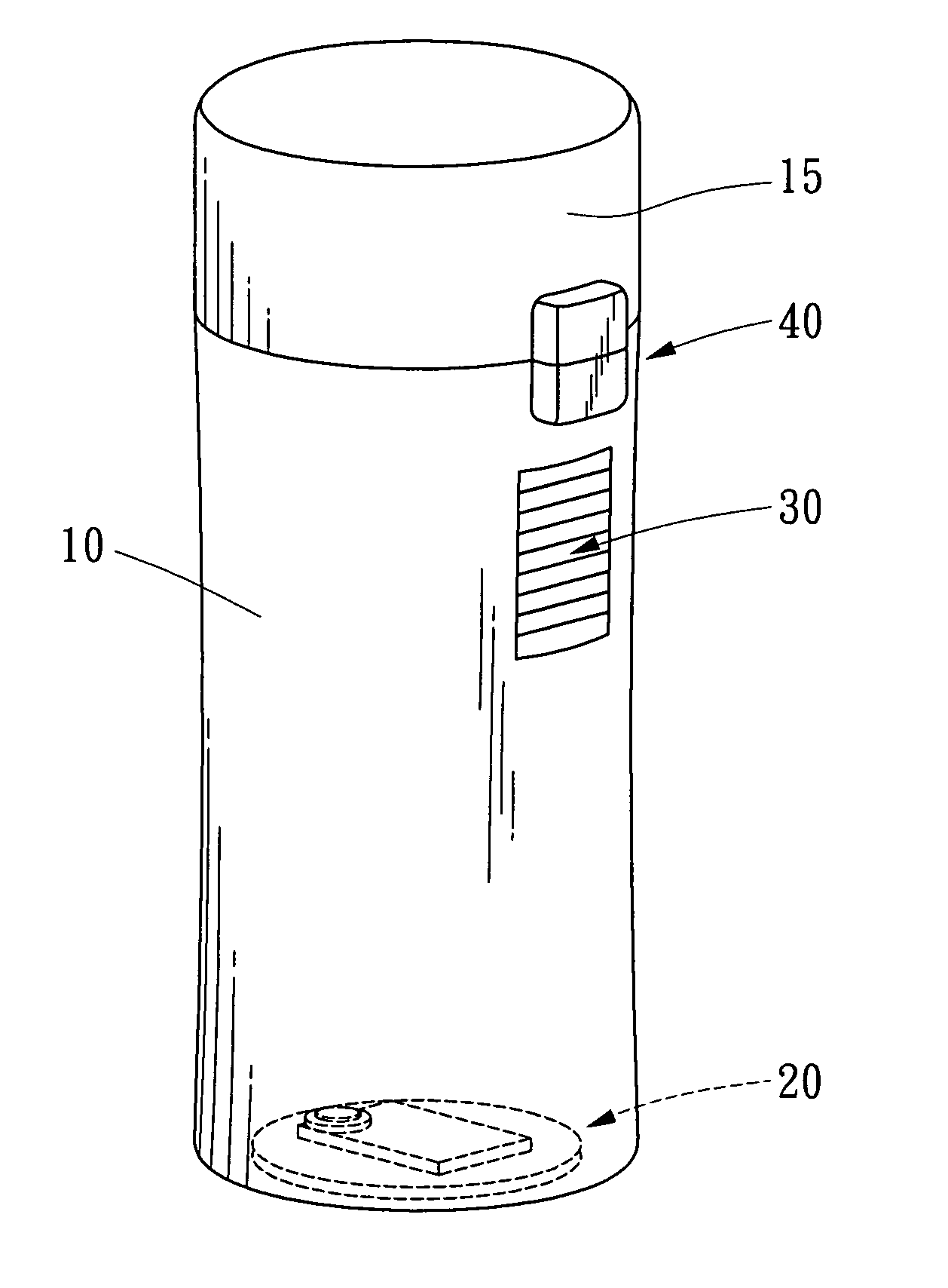
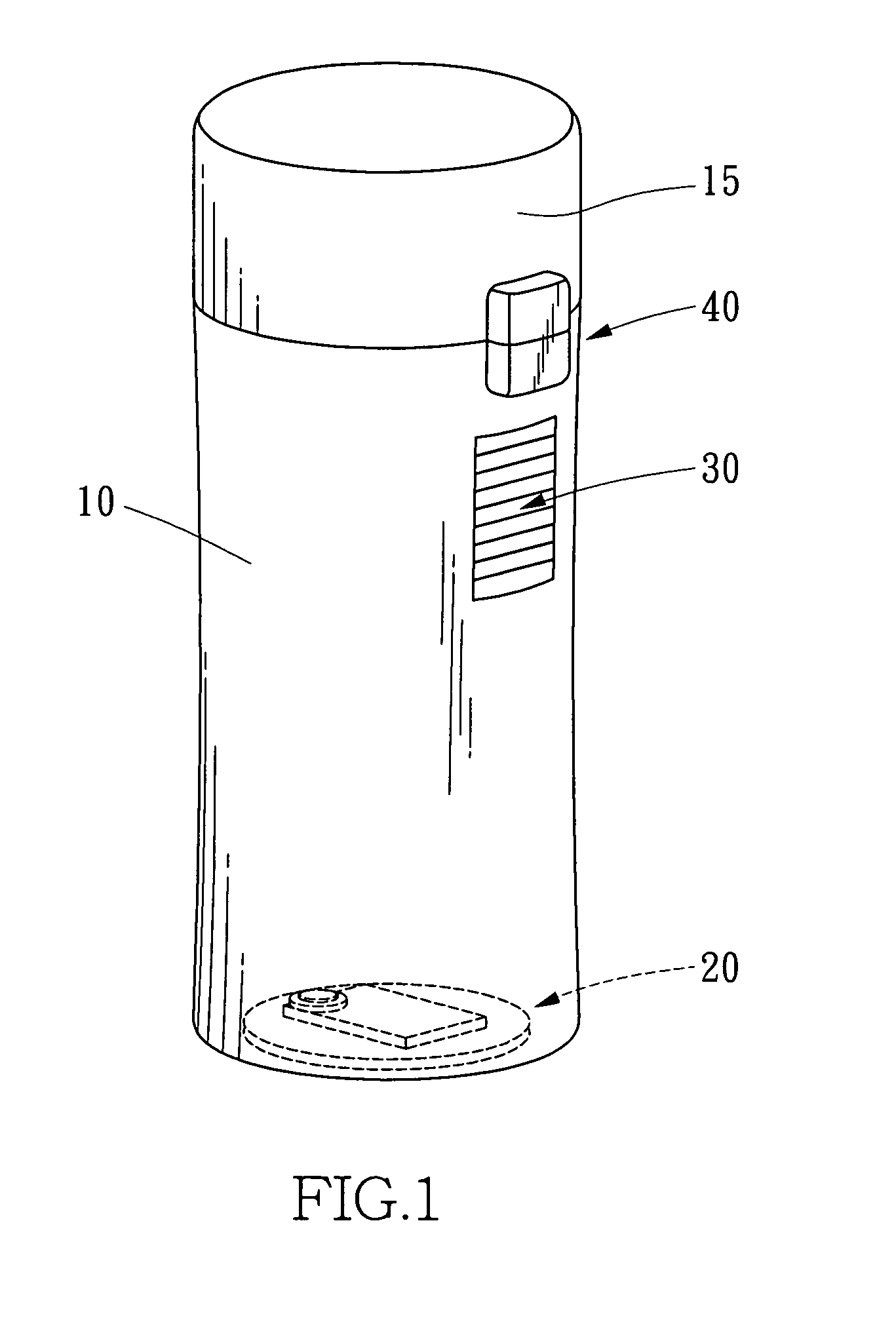
[0015]Referring to FIGS. 1 to 3, a safety bottle in accordance with a first preferred embodiment the invention comprises the following components as discussed in detail below.

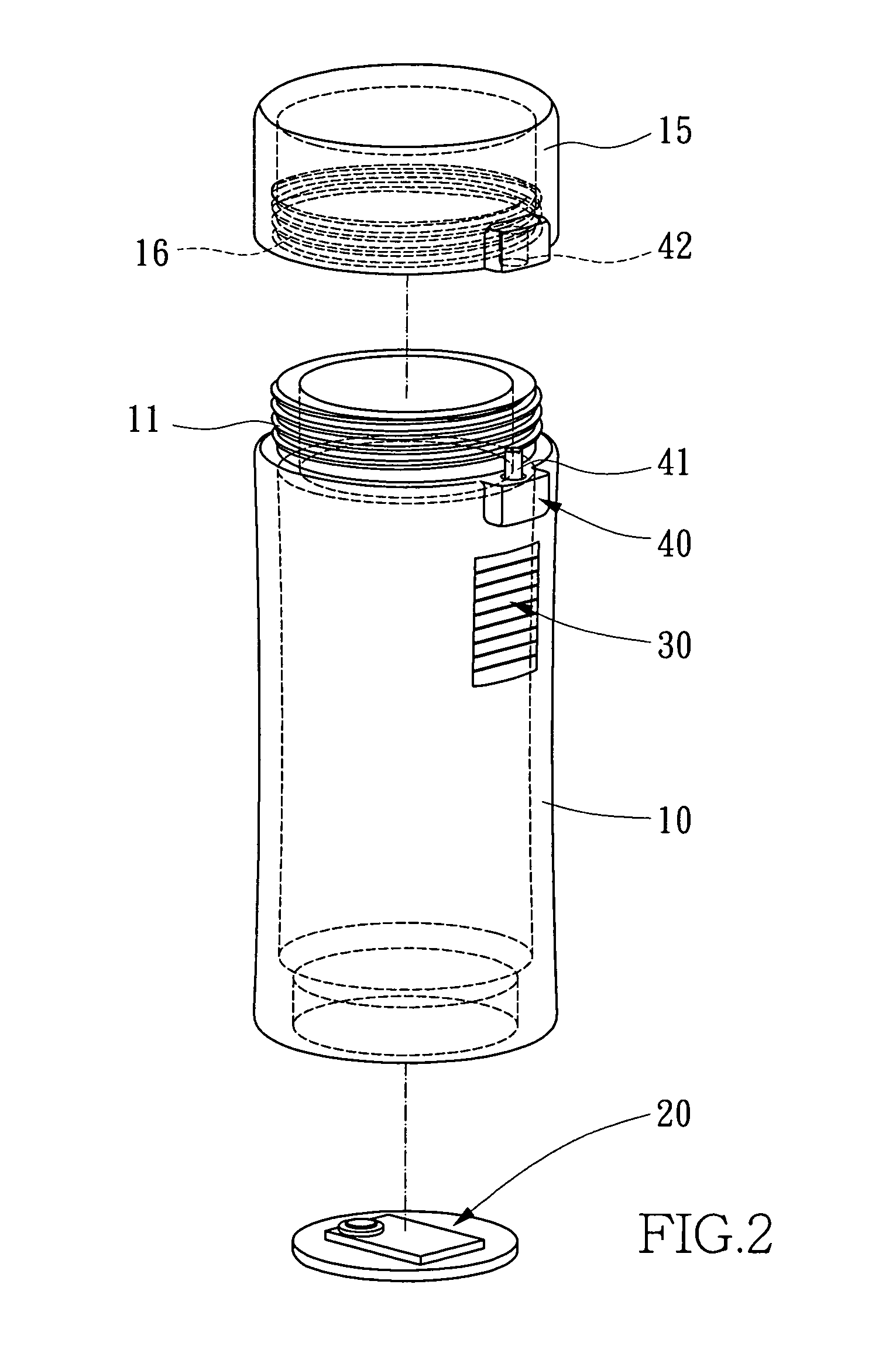
[0016]A cylindrical reservoir 10 is adapted to contain a quantity of liquid (e.g., pharmacies prescription filling). The reservoir 10 has an externally threaded neck 11. A cylindrical cap 15 has internal threads 16 adapted to secure to the neck 11. A magnetic lock 40 comprises a magnetically actuated spring bolt 41 formed on a periphery of the reservoir 10 proximate to a shoulder portion between the body of the reservoir 10 and the neck 11. The lock 40 further comprises a hole 42 formed on a lower edge of an outer surface of the cap 15. The hole 42 is shaped to complimentarily receive the bolt 41 and allow the bolt 41 to insert into or leave in a smooth manner.

[0017]A rectangular fingerprint scanner 30 is formed on the periphery of the reservoir 10 below the lock 40. A controller 20 comprises a disc 21 releasably


PUM


Abstract

A bottle cap includes a reservoir; a screw cap; a magnetic lock comprising a magnetically actuated spring bolt on the reservoir, and a hole on the cap; a fingerprint scanner on the reservoir; and a battery powered controller on bottom of the reservoir for fingerprint identification and fingerprint storing. In response to placing a finger on the fingerprint scanner, the fingerprint scanner and the controller are activated, the fingerprint scanner captures a fingerprint from the finger and converts the fingerprint into digital signals which are sent to the controller, the controller compares the digital signals with the fingerprint record(s), if matching the bolt will be compressed to clear the hole with the clearing being kept for a time to disengage the cap from the reservoir, and thereafter the controller and the fingerprint scanner will be deactivated and the bolt will bounce back to its locked position.

Description


Claims


Application Information

Patent Timeline
Owner WANG CHIU SUNG
Why Eureka
Try Eureka