Diverter cup assembly

Active Publication Date: 2011-12-22
SPECIALISED GASOLINEEUM SERVICES GROUP
View PDF7 Cites 0 Cited by
  • Summary
  • Abstract
  • Description
  • Claims
  • Application Information

AI Technical Summary

Benefits of technology

[0015]The improvements to be described in more detail hereinafter include a new assembly for mounting the diverter cup using separate housing parts slidable upon a tubular body and connected through the diverter cup itself, with associated limit stops on the tubular body acting upon the housing parts directly or indirectly through bearings to ensure that whenever

Problems solved by technology

During the extraction of conventional cleaning tools from the well, additional debris can be dislodged, such as from the wall of the casing, thereby undoing much of the cleaning work already performed.
This pushing together with the “swiping” effect by contact within the hole causes the diverter cup 5 to “squat” or shorten to a wider profile, making it much more prone to da

Method used


Image

  • Diverter cup assembly
  • Diverter cup assembly
  • Diverter cup assembly

Examples


Embodiment Construction

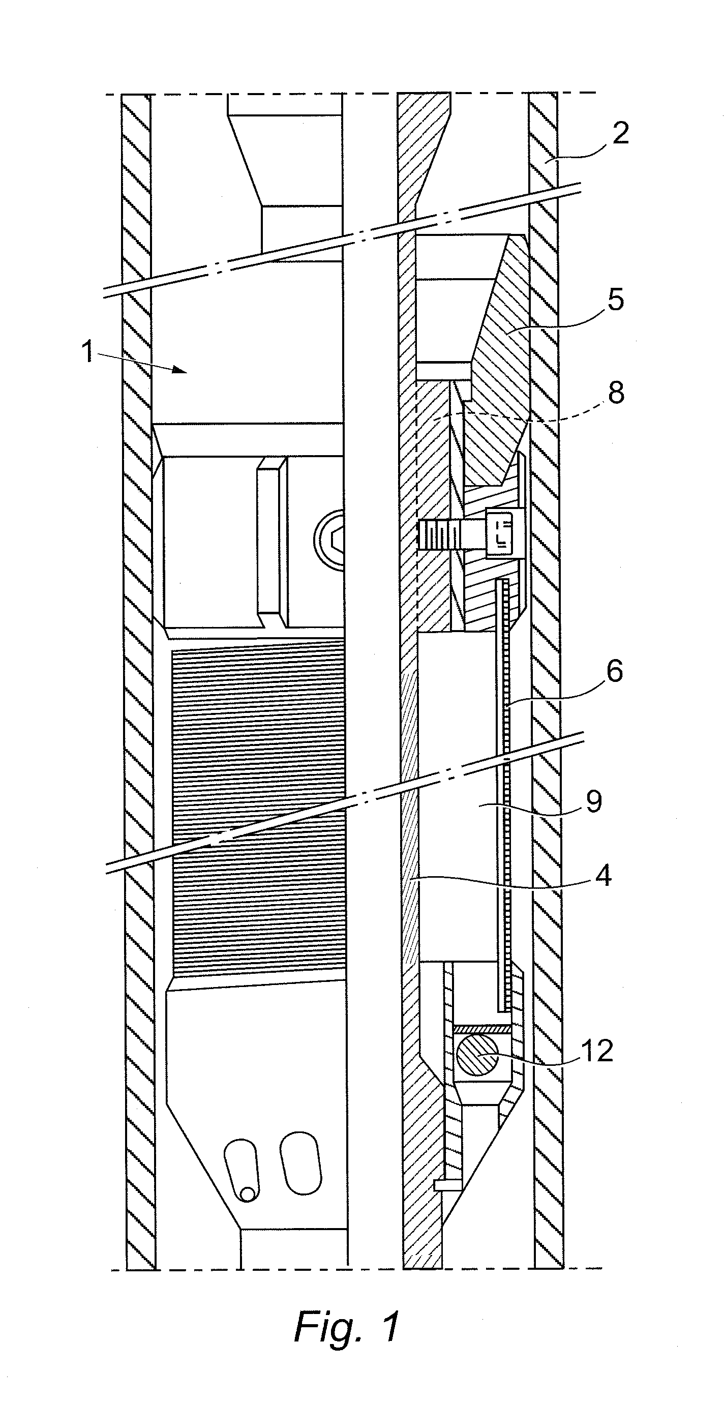
[0042]Referring to FIG. 3, this shows an upper end of a cleaning tool 101, which, in all other respects except as illustrated in FIG. 3, is the same as the cleaning tool 1 shown in FIG. 1 and described above.

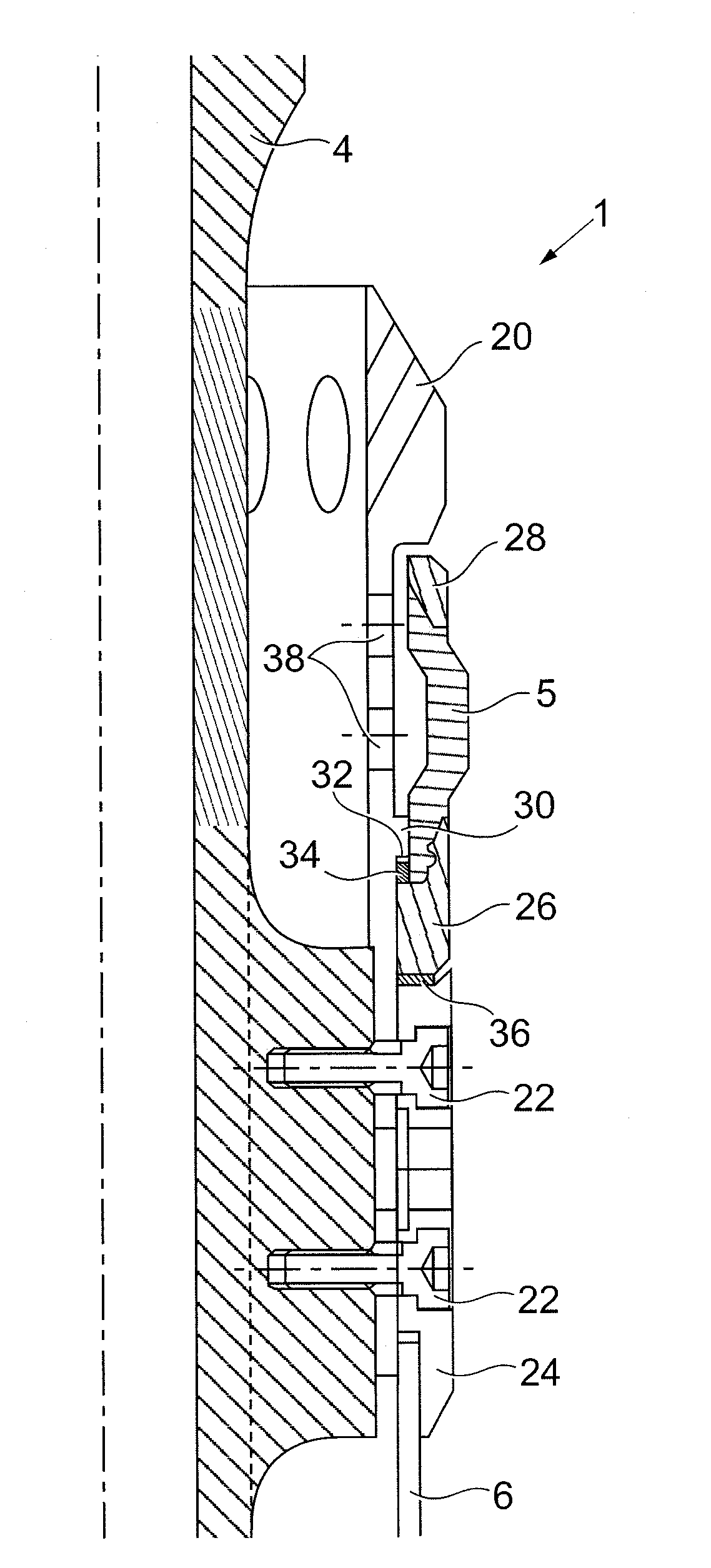
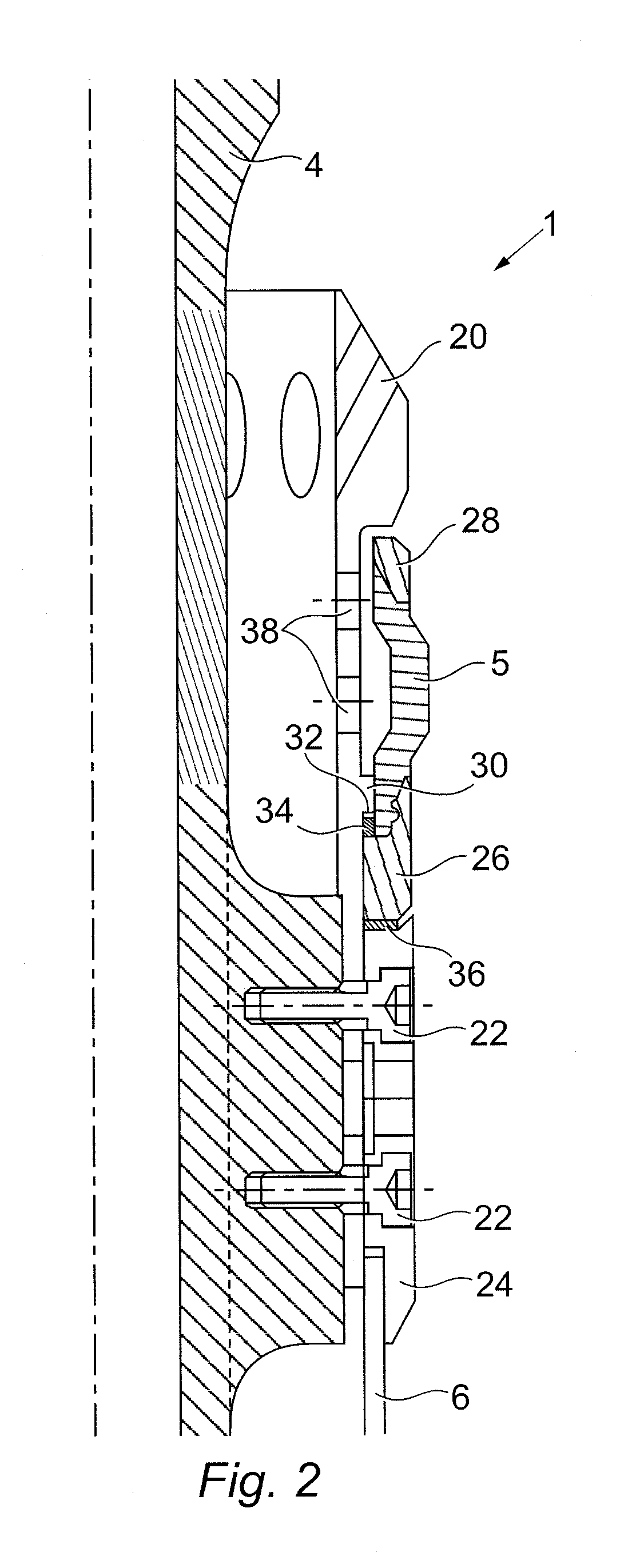
[0043]The cleaning tool 101 includes a diverter cup assembly 102 which includes a tubular body 120 having attachment means in the form of screws 122 (only one shown) for attaching the tubular body 120 to a mandrel 104 of a downhole string 103.

[0044]The diverter cup assembly 102 also includes a diverter cup 105, which is a resilient swab cup.

[0045]The diverter cup 105 is located concentrically around the tubular body 120 and has an arcuate form, with a larger outer diameter at its centre compared to its upper and lower ends, which are seated on the tubular body 120. The diverter cup 105 has an approximately equal thickness throughout.

[0046]The tubular body 120 includes at least one aperture 121 located behind the arc of the diverter cup 105, to allow deformation of the diverter cup


PUM


Abstract

A downhole cleaning tool for cleaning a casing is provided with a diverter cup assembly (102) including a housing (126) and a resilient swab cup (105) slidably mounted on a tubular body (120) with an increased external diameter portion 128 defining at either end upper and lower limit stops (130, 132), and sized to make provision for a gap (136) which allows a sliding movement of the swab cup such that only one of limit stops (130, 132) engages to always pull the swab cup via optional bearings (134) at each extremity of the sliding travel according to whether the tool is being run in hole or pulled out of the hole. This means that the swab cup is not compressed into a squat oversize shape susceptible to contact damage, and is naturally drawn out to tend towards an elongate shape in either direction of tool motion.

Description


Claims


Application Information

Patent Timeline
Owner SPECIALISED GASOLINEEUM SERVICES GROUP
Why Eureka
Try Eureka