Flow discouraging systems and gas turbine engines

Active Publication Date: 2012-01-05
HONEYWELL INT INC
View PDF11 Cites 11 Cited by
  • Summary
  • Abstract
  • Description
  • Claims
  • Application Information

AI Technical Summary

Benefits of technology

[0008]In an embodiment, by way of example only, a flow discouraging system includes a stator assembly, a rotor assembly, and a plurality of fingers. The stator assembly includes one or more stationary components forming a side wall, the side wall including an annular groove defined by an outer axially-extending surface, an inner axially-extending surface, and a radial surface extending between the outer and inner axially-extending surfaces. The rotor assembly is disposed adjacent to and spaced apart from the stator assembly to form a portion of a cavity and includes an annular rim extending at least partially into the annular groove. A plurality of fingers is disposed in the annular groove and extends from the one or more stationary components the annular rim.
[0009]In another embodiment, by of example only, a gas turbine engine includes a compressor section, a combustion section a

Problems solved by technology

However, because the extraction of cooling air does not contribute to providing power to the turbine for engine operation, providing an excessive q

Method used


Image

  • Flow discouraging systems and gas turbine engines
  • Flow discouraging systems and gas turbine engines
  • Flow discouraging systems and gas turbine engines

Examples


Embodiment Construction

[0017]The following detailed description is merely exemplary in nature and is not intended to limit the inventive subject matter or the application and uses of the inventive subject matter. In particular, although the inventive subject matter is described in the context of turbofan gas turbine engines, the inventive subject matter may be implemented in turbojet, turboprop, turboshaft, auxiliary power generation and pneumatic pressure generation gas turbine engines or any other engine in which a flow discouraging system may be useful. Furthermore, there is no intention to be bound by any theory presented in the preceding background or the following detailed description.

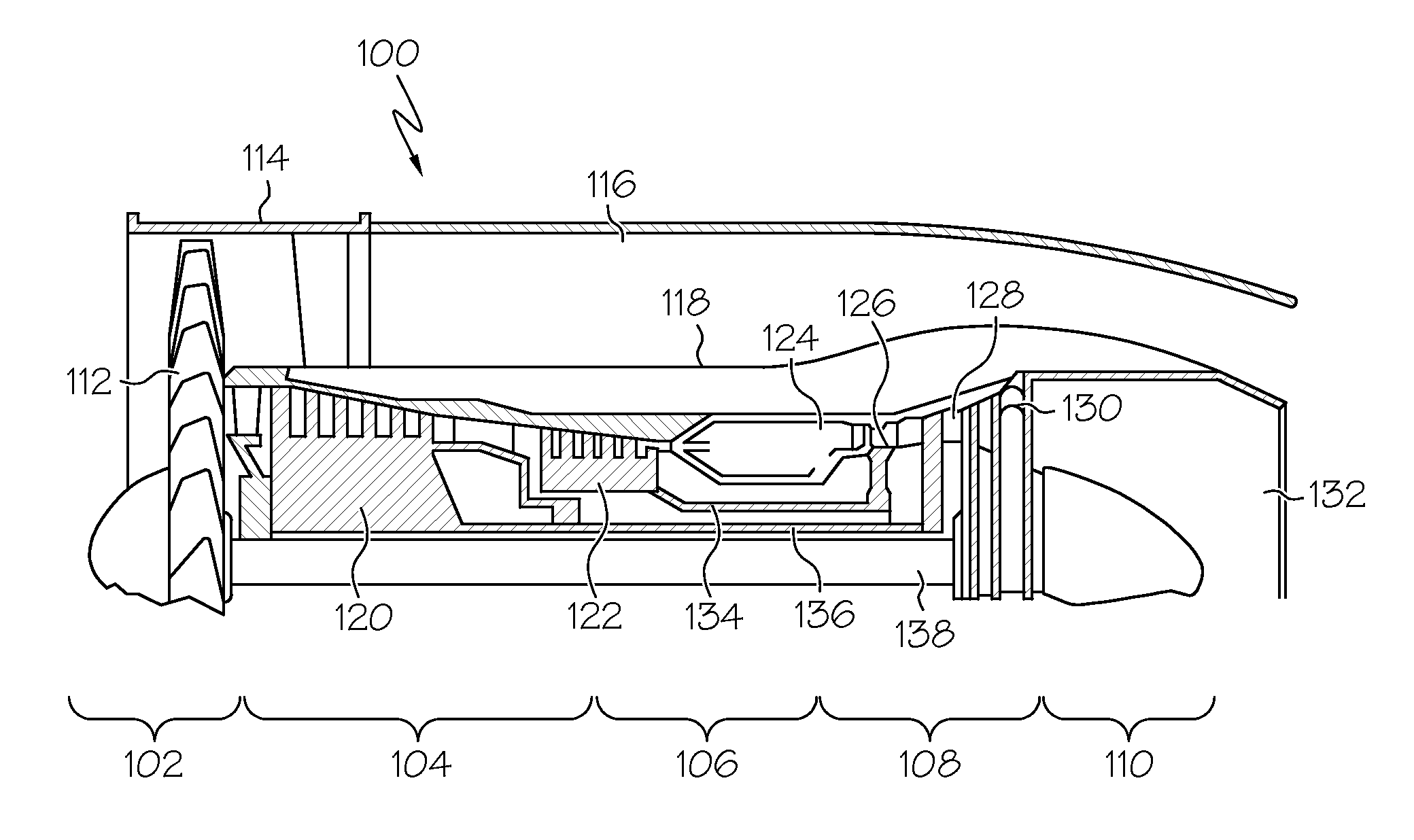
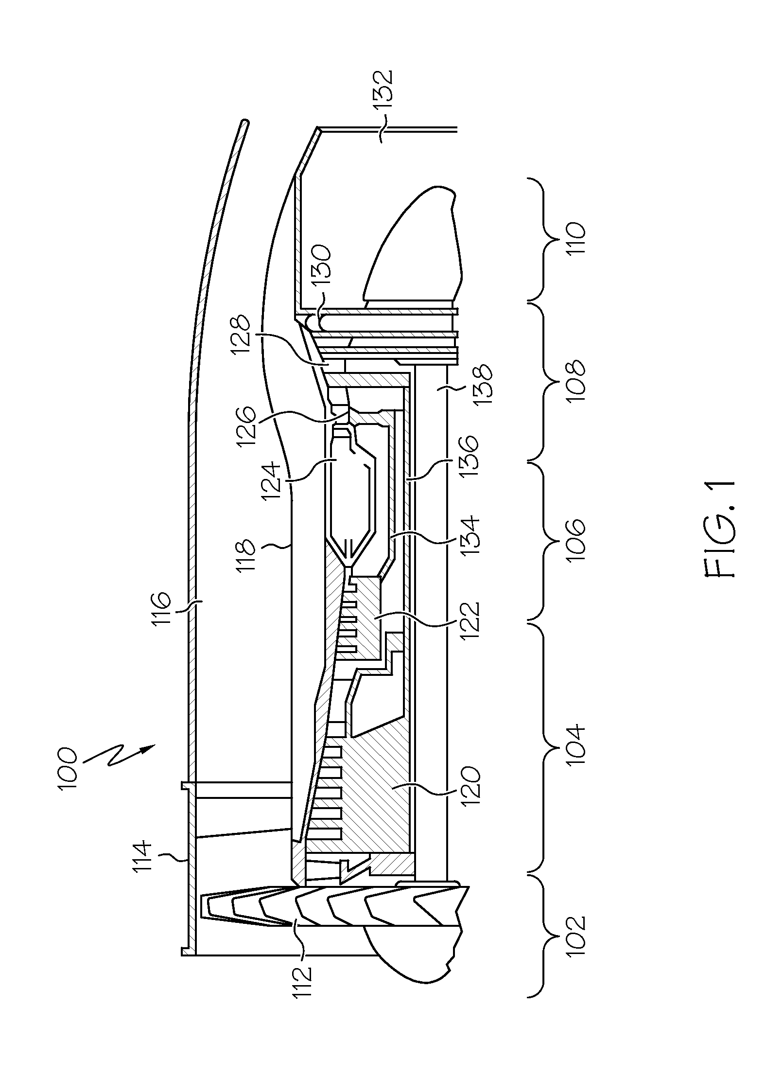
[0018]FIG. 1 is a simplified schematic of a gas turbine engine 100, according to an embodiment. In accordance with an embodiment, the gas turbine engine 100 may include a system that maintains a flow of hot combusted air along a designated flowpath by reducing or preventing the leakage of the hot combusted air into spaces


PUM


Abstract

A flow discouraging system includes a stator assembly, a rotor assembly, and a plurality of fingers. The stator assembly includes one or more stationary components forming a side wall, the side wall including an annular groove defined by an outer axially-extending surface, an inner axially-extending surface, and a radial surface extending between the outer and inner axially-extending surfaces. The rotor assembly is disposed adjacent to and spaced apart from the stator assembly to form a portion of a cavity and includes an annular rim extending at least partially into the annular groove. The plurality of fingers is disposed in the annular groove and extends from the one or more stationary components the annular rim.

Description


Claims


Application Information

Patent Timeline
Owner HONEYWELL INT INC
Why Eureka
Try Eureka