Display device

a display device and display technology, applied in the field of display, can solve the problems of distortion of optical film, deterioration of display quality of lcd panel, and warping of optical film, so as to avoid distortion of optical film and improve display quality

Active Publication Date: 2012-06-14
AU OPTRONICS CORP
View PDF4 Cites 5 Cited by
  • Summary
  • Abstract
  • Description
  • Claims
  • Application Information

AI Technical Summary

Benefits of technology

The present invention provides an improved way for displaying images without distorted or damaged areas caused by external light sources. This is achieved through a special design where a layer called a pad is placed between the display panel and the optical film. By doing this, any unwanted light from outside will be blocked out before it reaches the optical film, resulting in better image quality.

Problems solved by technology

This patent describes how thin and lightweight flat panels can now replace traditional CRT displays. However, these new technologies require a backlight system that efficiently removes excessive heat without causing distortions. Additionally, there is a problem where the optical films used in the backlight module expand differently due to temperature changes caused by the light sources themselves. These issues affect the performance of the LC panel and degrade its overall image quality.

Method used


Image

  • Display device
  • Display device
  • Display device

Examples


Embodiment Construction

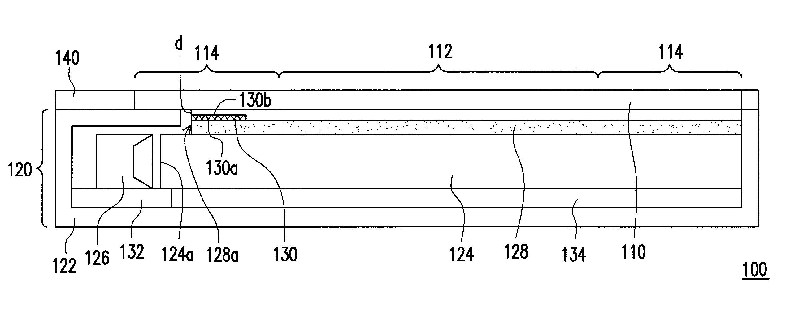
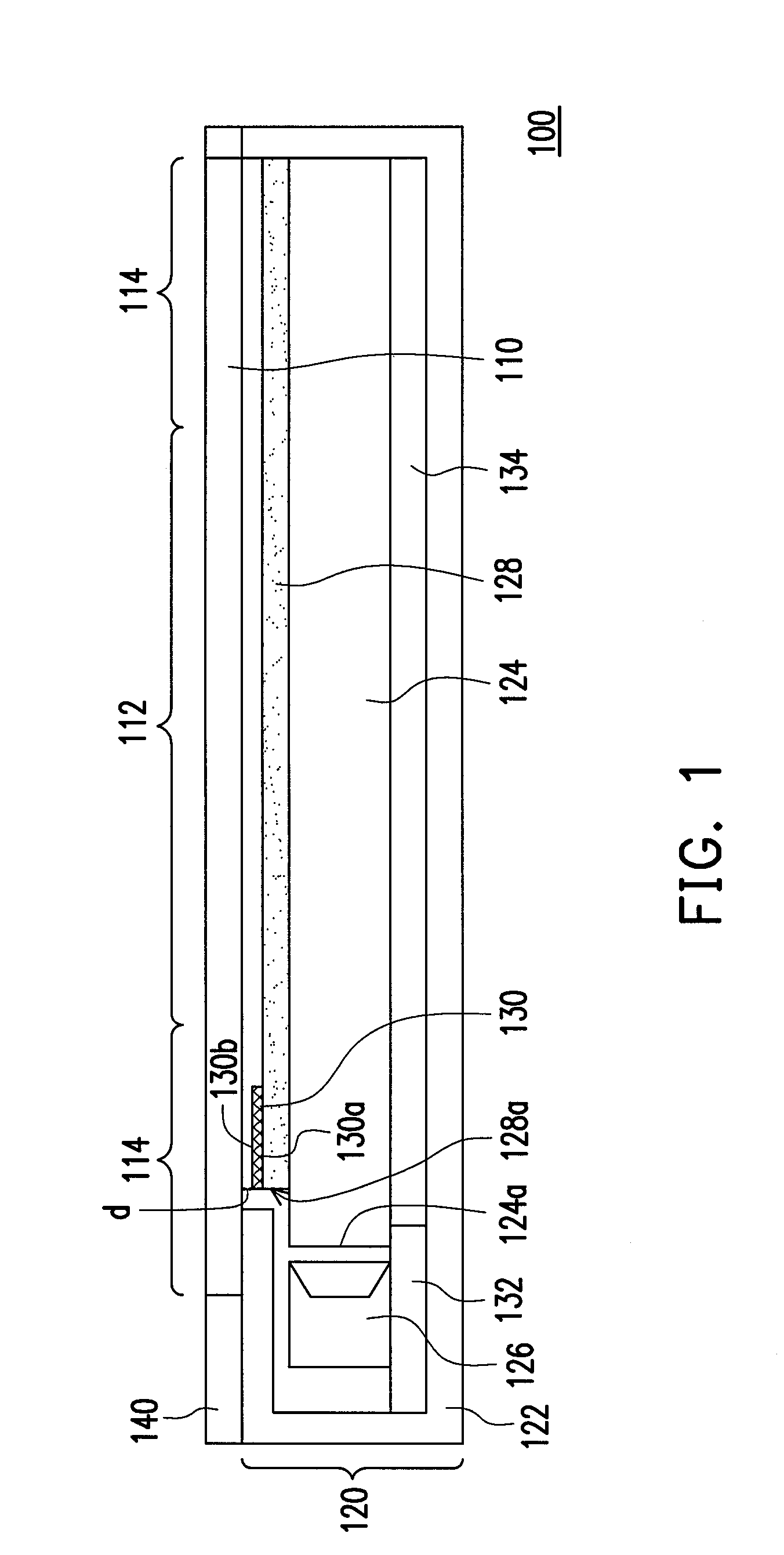
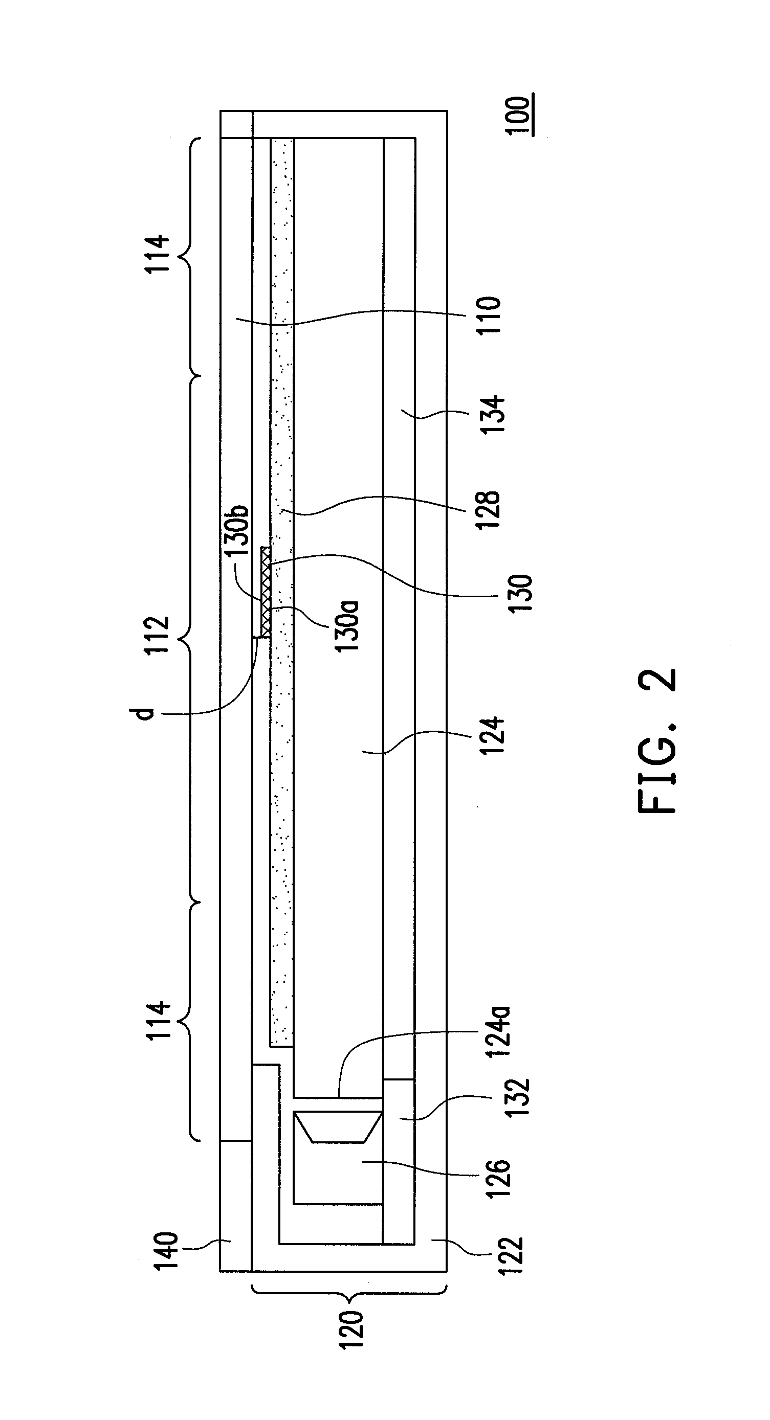
[0024]FIG. 1 is a schematic cross-sectional view illustrating an LCD according to an embodiment of the invention. With reference to FIG. 1, the display 100 includes a display panel 110 and a backlight module 120. The backlight module 120 is configured below the display panel 110. Namely, the display panel 110 is configured on the light emitting surface of the backlight module 120, so as to receive the light coming from the backlight module 120 and thereby perform the display function. In this embodiment, the display 100 further includes a front bezel 140, and the display panel 110 is assembled to the front bezel 140 and the back plate 122 of the backlight module 120, so as to form the display 100. The display panel 110 of this embodiment is, for example, a transmissive LCD panel, a transflective LCD panel, or any other display panel suitable for applying the backlight source, which should not be construed as a limitation to the invention. The display panel 110 has a display region 112


PUM


Abstract

A display includes a display panel and a backlight module. The backlight module is configured below the display panel and includes a light guide plate (LGP), a light source, an optical film, and a pad. The light source is located near the LGP. The optical film is configured on the LGP. The pad is located between the optical film and the display panel. A first surface of the pad is fixed to the optical film, and a second surface of the pad is slidable relative to the display panel.

Description


Claims


Application Information

Patent Timeline
Owner AU OPTRONICS CORP
Why Eureka
Try Eureka