Printing control device, storage medium storing printing control program, and printing control method
a printing control and control device technology, applied in the direction of digital output to print units, instruments, digital computers, etc., can solve the problems of difficulty in indicating a change in the print setting information, difficulty in performing such editing, and occurrence of various quality deficiencies such as the disappearance of thin lines
- Summary
- Abstract
- Description
- Claims
- Application Information
AI Technical Summary
Benefits of technology
Problems solved by technology
Method used
Image

Examples
first embodiment
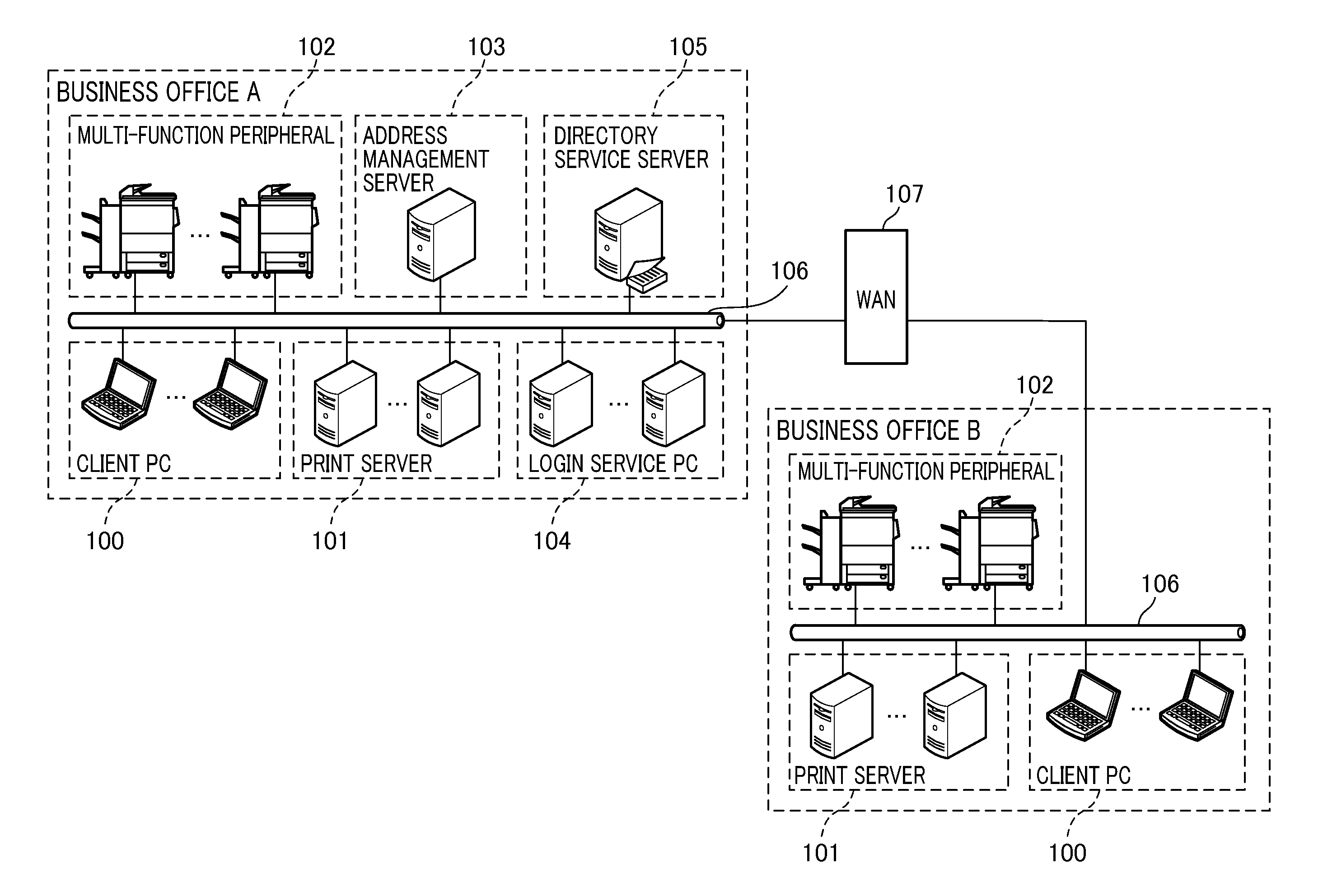
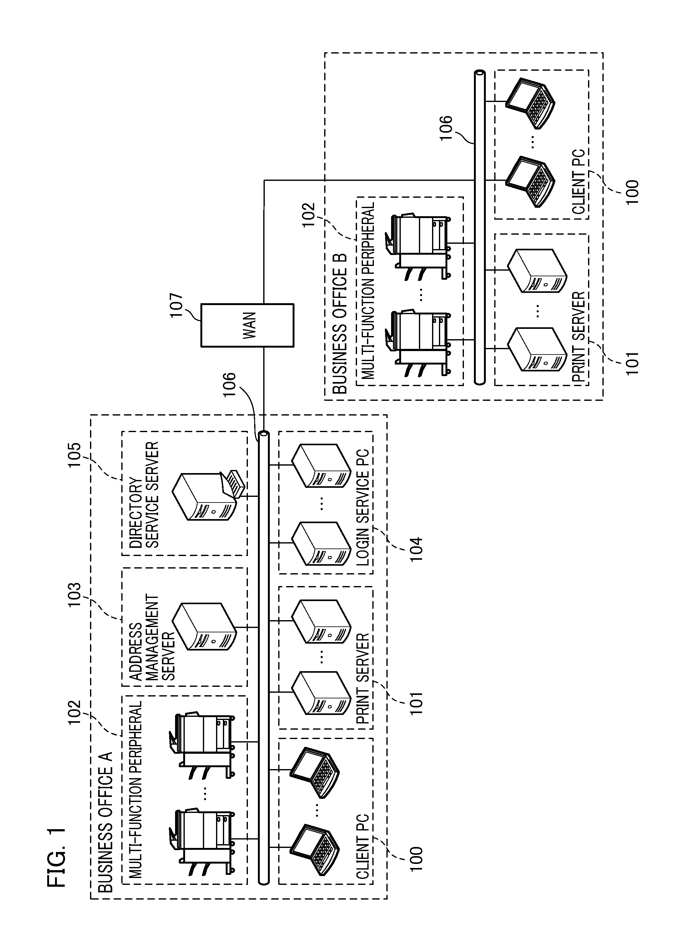
[0040]FIG. 1 is a diagram illustrating an example of the configuration of a system including a client PC, a print server (printing control device), an address management server, and a printing apparatus. As shown in a “business office A” in FIG. 1, the printing system of the present embodiment includes one or a plurality of client PCs 100, one or a plurality of print servers 101, and one or a plurality of multi-function peripherals 102. As an example, the client PCs 100 are assigned to each user, the print servers 101 are provided for each floor of the business office A, and the multi-function peripherals 102 are provided for each floor of the business office A. Furthermore, an address management server 103, one or a plurality of login service PCs 104 (e.g., provided for each floor), and a directory service server 105 are connected to each other via a local area network (LAN) 106.
[0041]A virtual printer driver is installed in the client PC 100. The virtual printer driver generates a pr
second embodiment
[0130]Next, a description will be given of a printing system according to a second embodiment of the present invention. The printing system in the second embodiment has the same configuration as that of the printing system in the first embodiment shown in FIG. 1, and includes a client PC, a print server (printing control device), an address management server, and a printing apparatus. The printing system of the second embodiment includes special processing when a specific drawing process is a color / monochrome print function or an integration print function. More specifically, special processing includes processing of a print job in the EMFSPOOL format as well as processing of a print job in the EMFSPOOL format when the specific drawing process is the expansion / reduction print function.
[0131]FIG. 16 is a flowchart illustrating an example of the seventh control processing procedure in the printing system of the present invention. This procedure corresponds to the processing procedure
third embodiment
[0137]In the processes described in the second embodiment, a non-standard paper size is set to the original paper size in print settings to be transmitted to the actual output printer driver 408 so as to perform print data transmission if the printer driver 408 does not support the expansion / reduction print function. In the third embodiment, printing can still be made even if there is a function (two-sided printing or the like) not available for a non-standard paper size. In the third embodiment, the processes in steps SC1600 to SC1605 are the same as those described in the second embodiment, and thus, a detailed description thereof will be omitted.
[0138]If the printer driver 408 does not support the expansion / reduction print function in step SC1604, the job management service 403 performs processing for expanding or reducing a print job in the EMFSPOOL format in step SC1606. Next, the job management service 403 acquires a list of supported paper sizes from the actual output printe
PUM
 Abstract
Description
Claims
Application Information
 - R&D Engineer
- R&D Manager
- IP Professional
- Industry Leading Data Capabilities
- Powerful AI technology
- Patent DNA Extraction
Browse by: Latest US Patents, China's latest patents, Technical Efficacy Thesaurus, Application Domain, Technology Topic.
© 2024 PatSnap. All rights reserved.Legal|Privacy policy|Modern Slavery Act Transparency Statement|Sitemap