Heat pipe structure

a technology of heat pipe and heat pipe body, which is applied in the direction of lighting and heating apparatus, semiconductor devices, and semiconductor/solid-state device details. it can solve the problems of internal capillaries, sintered metal powder or mesh capillaries, and internal capillaries, so as to improve the heat pipe structure and improve heat conduction efficiency and heat transfer efficiency.

Active Publication Date: 2013-08-22
ASIA VITAL COMPONENTS SHENZHEN CO LTD
View PDF26 Cites 12 Cited by
  • Summary
  • Abstract
  • Description
  • Claims
  • Application Information

AI Technical Summary

Benefits of technology

The technical effect that this innovation improves on existing structures for better thermal management by allowing more efficient energy exchange between two objects without adding extra weight or complexity compared with traditional methods like water pipes.

Problems solved by technology

There has developed an improved method called microplenier technology for making smaller heatpipes without compromising their effectiveness due to factors including reducing pressure drop caused by gravity during operation. These improvements include increasing the size of the fins within the heatpipe while maintaining good surface tension between them. Additionally, there may exist issues where the heat conduction process becomes impaired when trying to reduce thickness of the device's housing.

Method used


Image

  • Heat pipe structure
  • Heat pipe structure
  • Heat pipe structure

Examples


Embodiment Construction

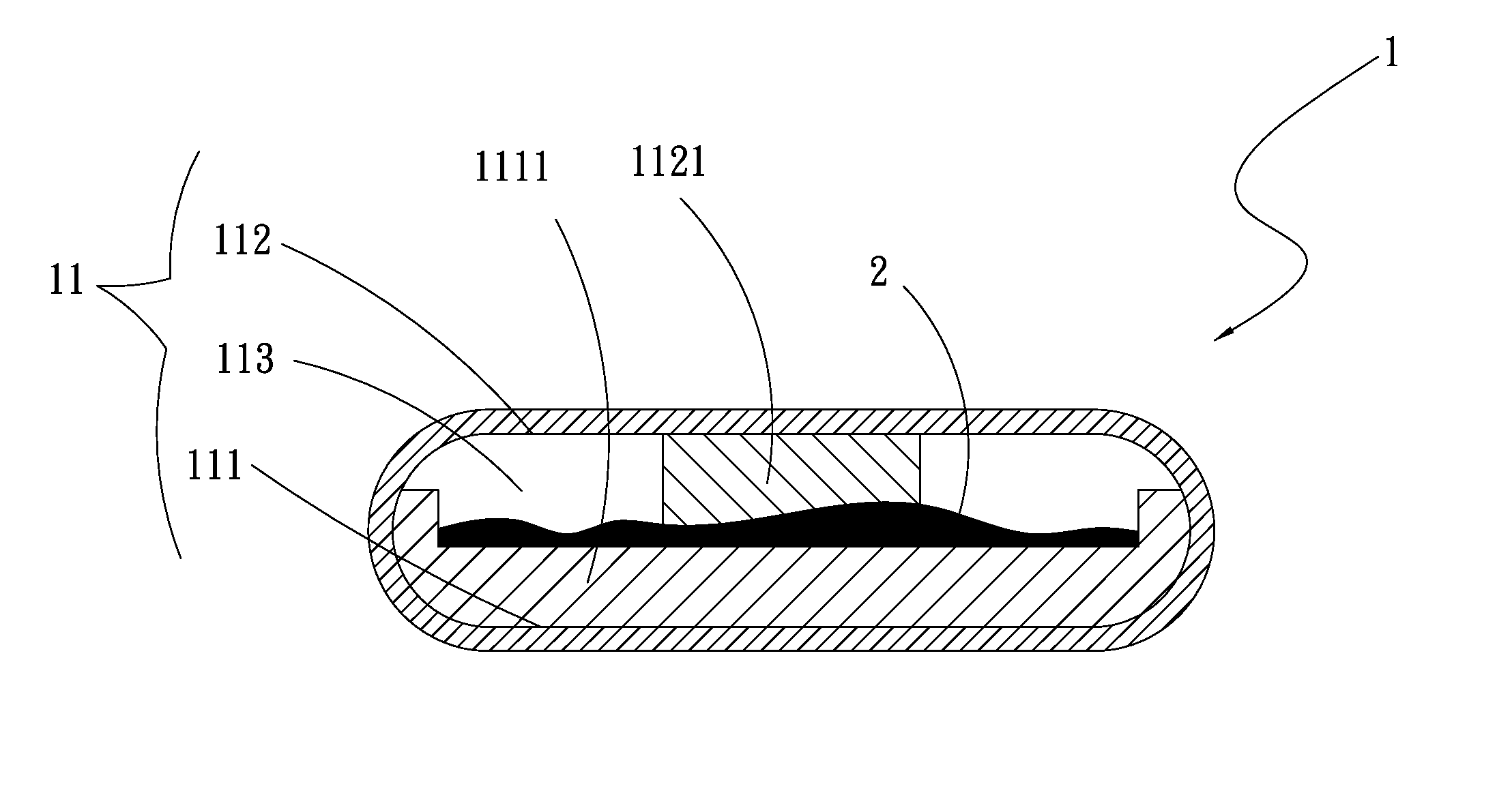
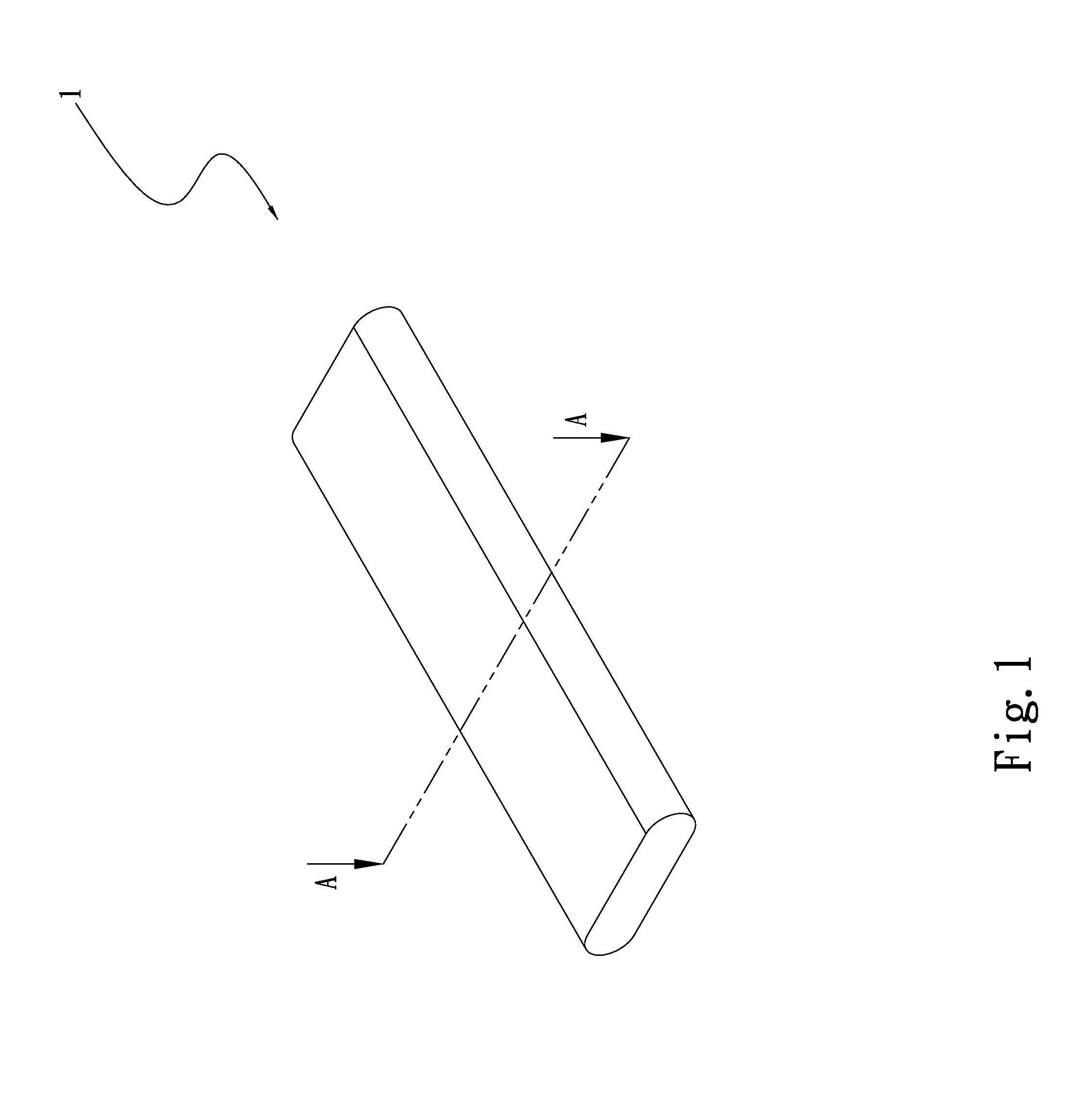
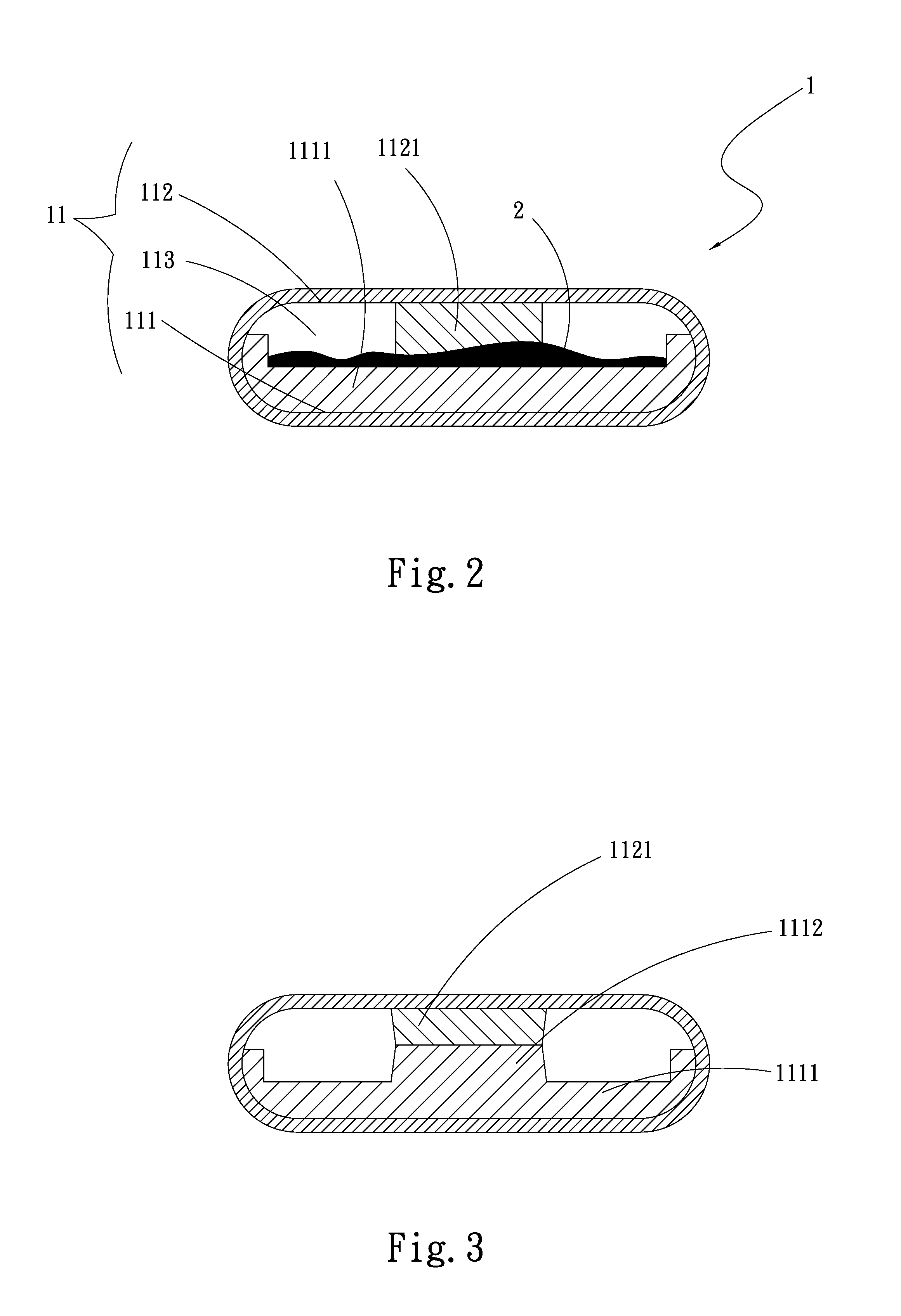
[0027]Please refer to FIGS. 1 and 2. FIG. 1 is a perspective view of a first embodiment of the heat pipe structure of the present invention. FIG. 2 is a sectional view taken along line A-A of FIG. 1. According to the first embodiment, the heat pipe structure of the present invention includes a main body 1 having a chamber 11. The chamber 11 has a first side 111 and a second side 112. A first capillary structure 1111 and a second capillary structure 1121 are respectively disposed on the first and second sides 111, 112. A working fluid 2 is filled in the chamber 11. The first capillary structure 1111 has a radial extension range larger than or equal to one half of the circumference of the inner wall face of the chamber 11 and larger than the radial extension range of the second capillary structure 1121. One side of the first capillary structure 1111 is connected with the second capillary structure 1121. The first and second capillary structures 1111, 1121 and the inner wall face of the c


PUM


Abstract

A heat pipe structure includes a main body having a chamber. The chamber has a first side and a second side. A first capillary structure and a second capillary structure are respectively disposed on the first and second sides. A working fluid is filled in the chamber. The first capillary structure has a radial extension range larger than or equal to one half of a circumference of inner wall face of the chamber and larger than a radial extension range of the second capillary structure. The first and second capillary structures are connected with each other. The first and second capillary structures and the inner wall face of the chamber together define at least one vapor passage. By means of the heat pipe structure, the amount of transferred heat is increased and the heat transfer efficiency is greatly enhanced.

Description


Claims


Application Information

Patent Timeline
Owner ASIA VITAL COMPONENTS SHENZHEN CO LTD
Why Eureka
Try Eureka