Liquid-discharging device, liquid stirring method, and liquid filling method

Inactive Publication Date: 2013-09-12
SEIKO EPSON CORP
View PDF1 Cites 7 Cited by
  • Summary
  • Abstract
  • Description
  • Claims
  • Application Information

AI Technical Summary

Benefits of technology

[0007]The present invention has been made to address the above-described circumstances, and an object of the

Problems solved by technology

In such a liquid-discharging device, however, there are cases where air (air bubbles) enters the reservoir section.
T

Method used


Image

  • Liquid-discharging device, liquid stirring method, and liquid filling method
  • Liquid-discharging device, liquid stirring method, and liquid filling method
  • Liquid-discharging device, liquid stirring method, and liquid filling method

Examples


embodiments

Configuration Example of Printer 1

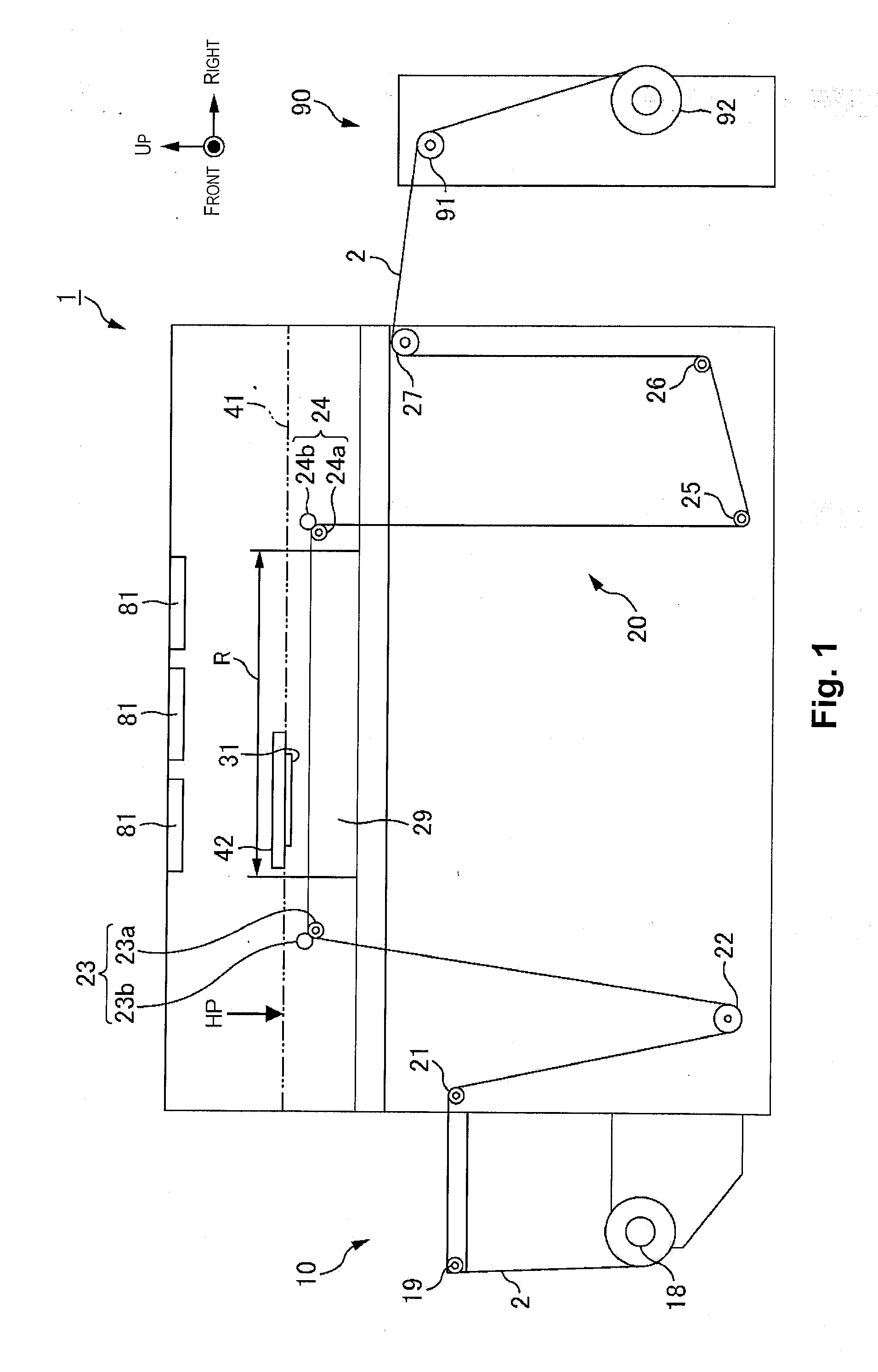
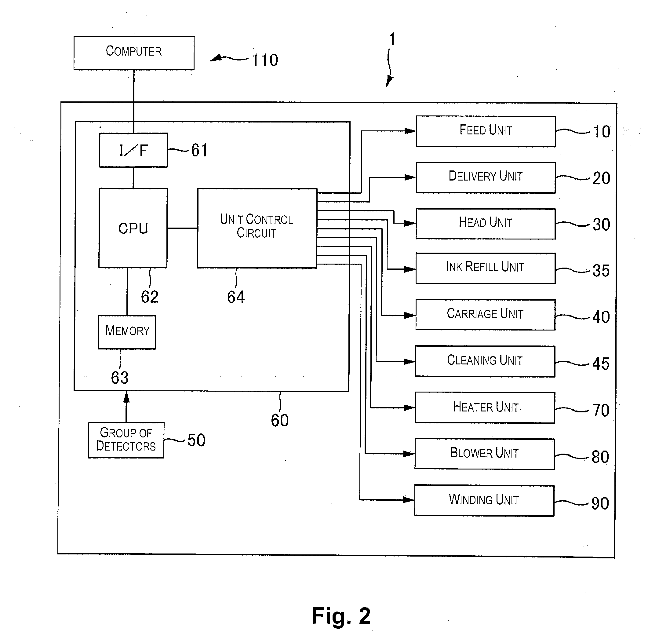
[0041]A configuration example of the printer 1 (in the present embodiment, an ink jet printer, in particular, a lateral scan type label printing machine) as an example of the liquid-discharging device will be described with reference to FIG. 1 and FIG. 2. FIG. 1 is a schematic diagram that illustrates a configuration of the printer 1. FIG. 2 is a block diagram that illustrates a configuration example of the printer 1.

[0042]In the following descriptions, “vertical direction” and “horizontal direction” are based on directions shown by arrows in FIG. 1. “Front-back direction” refers to a direction perpendicular to the paper in FIG. 1.

[0043]In the present embodiment, paper winded in a roll shape (hereinafter, referred to as “roll paper (continuous paper)”) is used as an example a medium on which the printer 1 records an image.

[0044]As shown in FIG. 1 and FIG. 2, the printer 1 according to the present embodiment has a delivery unit 20, a feed unit10, a plat


PUM


Abstract

A liquid ejection device includes a head section, a first liquid reservoir section, a supply passage, a second liquid reservoir section, an outgoing passage that sends liquid from the first liquid reservoir section to the second liquid reservoir section and includes a shared passage shared with the supply passage, a return passage that sends the liquid from the second liquid reservoir section to the first liquid reservoir section, and a controller. After the controller performs a stirring process of stirring the liquid by causing the liquid in the first liquid reservoir section to pass through the outgoing passage and subsequently causing the liquid in the second liquid reservoir section to pass through the return passage, the controller performs a process of flowing out a part of the liquid in the first liquid reservoir section toward the shared passage.

Description


Claims


Application Information

Patent Timeline
Owner SEIKO EPSON CORP
Why Eureka
Try Eureka