Airbag device

a technology of airbags and airbags, which is applied in the direction of pedestrian/occupant safety arrangements, vehicular safety arrangements, vehicle components, etc., can solve the problems of large volume of the bag main body, slow surface member movement speed, and long time until the bag main body is fully inflated and deployed, so as to achieve short time, reduce the effect of airbag capacity and short deployment tim

Active Publication Date: 2013-10-17
ASHIMORI INDS
View PDF12 Cites 0 Cited by
  • Summary
  • Abstract
  • Description
  • Claims
  • Application Information

AI Technical Summary

Benefits of technology

The present invention provides an improved air bag system that allows for quick expansion and deployment while maintaining its effectiveness. This makes it more efficient than existing systems.

Problems solved by technology

The technical problem addressed in this patent text is how to improve the efficiency and effectiveness of airbags in vehicles during accidental impacts. Specifically, it focuses on improving the deployment and protection of knee airbags that are placed inside the vehicle's instrument panels. This can be achieved through reducing the size of the bag main body while still maintaining its ability to deploy quickly and effectively.

Method used


Image

  • Airbag device
  • Airbag device
  • Airbag device

Examples


Embodiment Construction

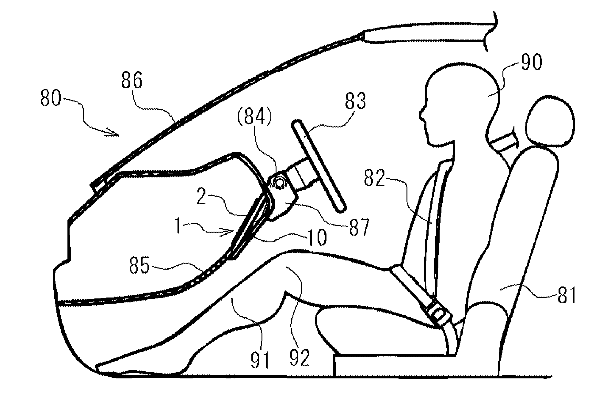
[0018]An embodiment of an airbag device of the present invention will be described below by referring to the attached drawings. In this embodiment, a knee airbag device is used as an example for explanation. The knee airbag device is an airbag device for protecting knees. The knee airbag device is mounted in a vehicle and protects an occupant seated on a seat (a driver's seat or a front occupant's seat). Moreover, the knee airbag device is disposed in front of the knee part of an occupant. The knee airbag device suppresses movement of the knee part of the occupant and protects mainly the knee part of the occupant. In the following, the knee airbag device disposed in an instrument panel in front of the driver's seat will be explained.

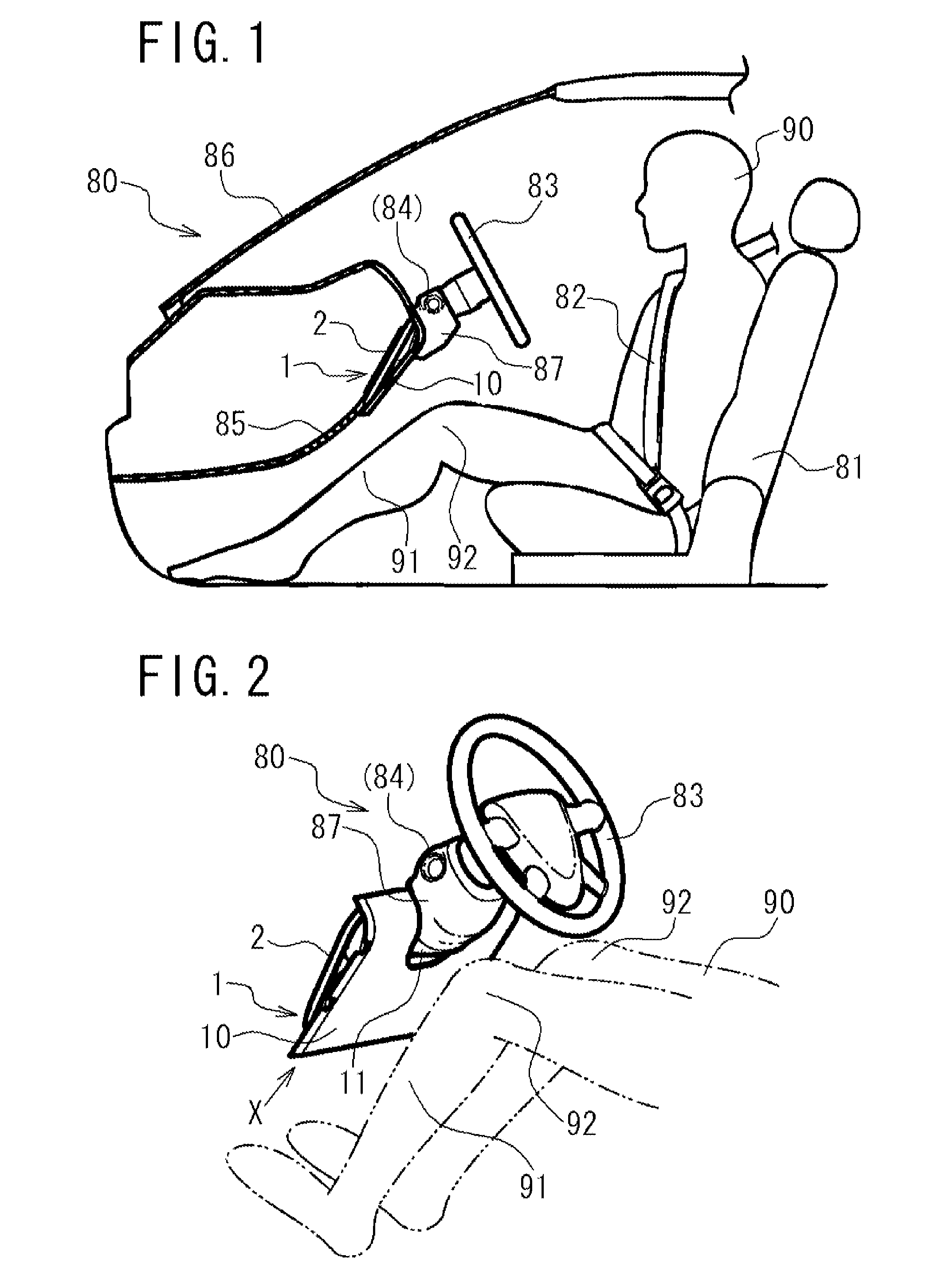
[0019]FIG. 1 is a cross-sectional diagram of a vehicle on which the knee airbag device of this embodiment is mounted. In FIG. 1, the vicinity of the driver's seat of the vehicle is illustrated when viewed from the side. In FIG. 1, a part of the vehicle 80 a


PUM


Abstract

An airbag is inflated and deployed in a short time, and a protective panel is moved rapidly. An airbag device (1) is disposed in a base section (2) of a vehicle. The airbag device (1) is provided with a protective panel (10) covering the base section (2), an airbag (20), and an inflator. The inflator inflates and deploys the airbag (20) by generating a gas. The airbag (20) has at least two standing portions (30) and inflates and deploys between the base section (2) and the protective panel (10). The standing portion (30) stands up from the base section (2) through inflation and moves the protective panel (10).

Description


Claims


Application Information

Patent Timeline
Owner ASHIMORI INDS
Why Eureka
Try Eureka