Test device and control method thereof

Inactive Publication Date: 2014-01-16
SAMSUNG ELECTRONICS CO LTD
View PDF2 Cites 1 Cited by
  • Summary
  • Abstract
  • Description
  • Claims
  • Application Information

AI Technical Summary

Benefits of technology

[0029]The adjusting may include, if the signal value is greater than the predetermined target value and a difference between the signal value and the predetermined target value is greater than or equal to a predetermined standard value, reducing light emitted from the light emitting element such that the difference decreases below the standard value, and when the difference is less than the standard value, decreasing the exposure level of the light receiving element.
[0030]The adjusting may include, if the signal value is less than the predetermined target value and a difference between the signal value and the predetermined target value is greater than or equal to a predetermined standard value, increasing light emitted from the light emitting element such that the difference decreases below the standard value, and once the difference is less than the standard value, increasing the exposure level of the light receiving element.

Problems solved by technology

This may lead to variations in assay results and reduce the reliability of such assay results.

Method used


Image

  • Test device and control method thereof
  • Test device and control method thereof
  • Test device and control method thereof

Examples


Example

[0058]Reference will now be made in detail to exemplary embodiments, examples of which are illustrated in the accompanying drawings, wherein like reference numerals refer to like elements throughout.

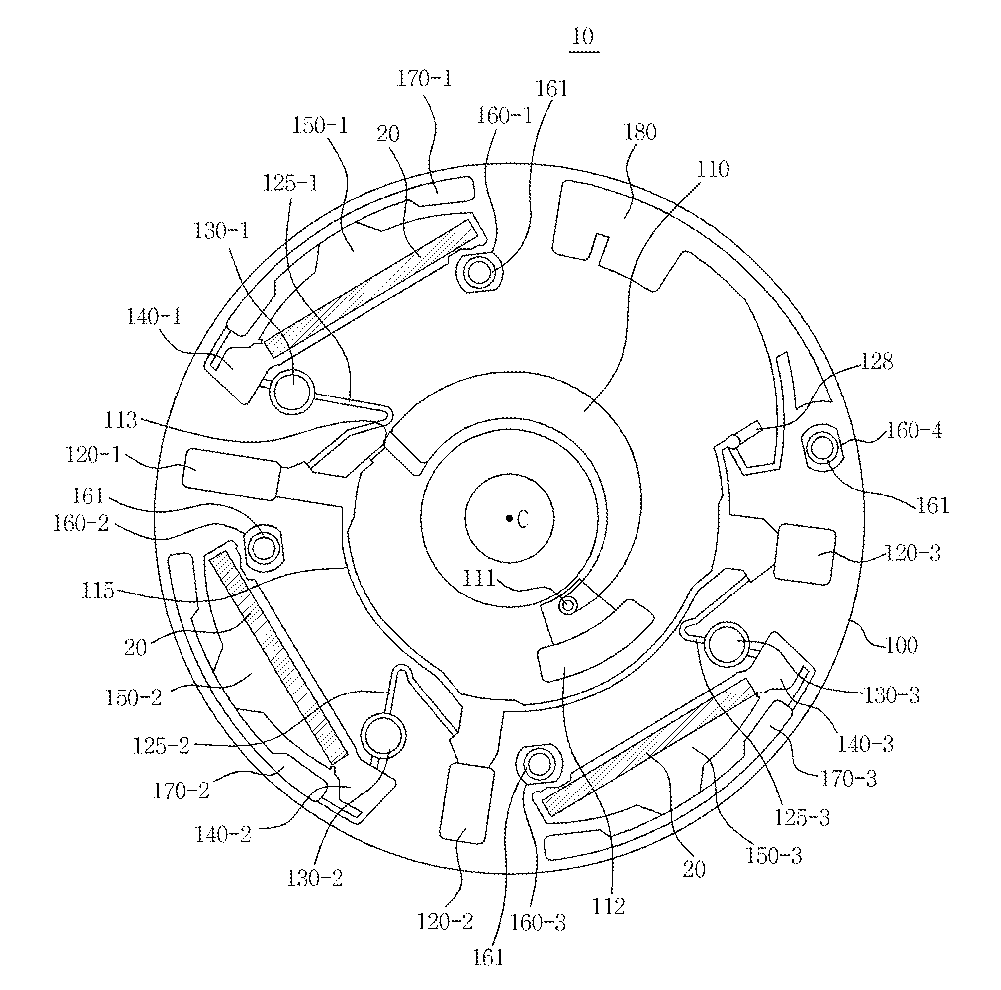
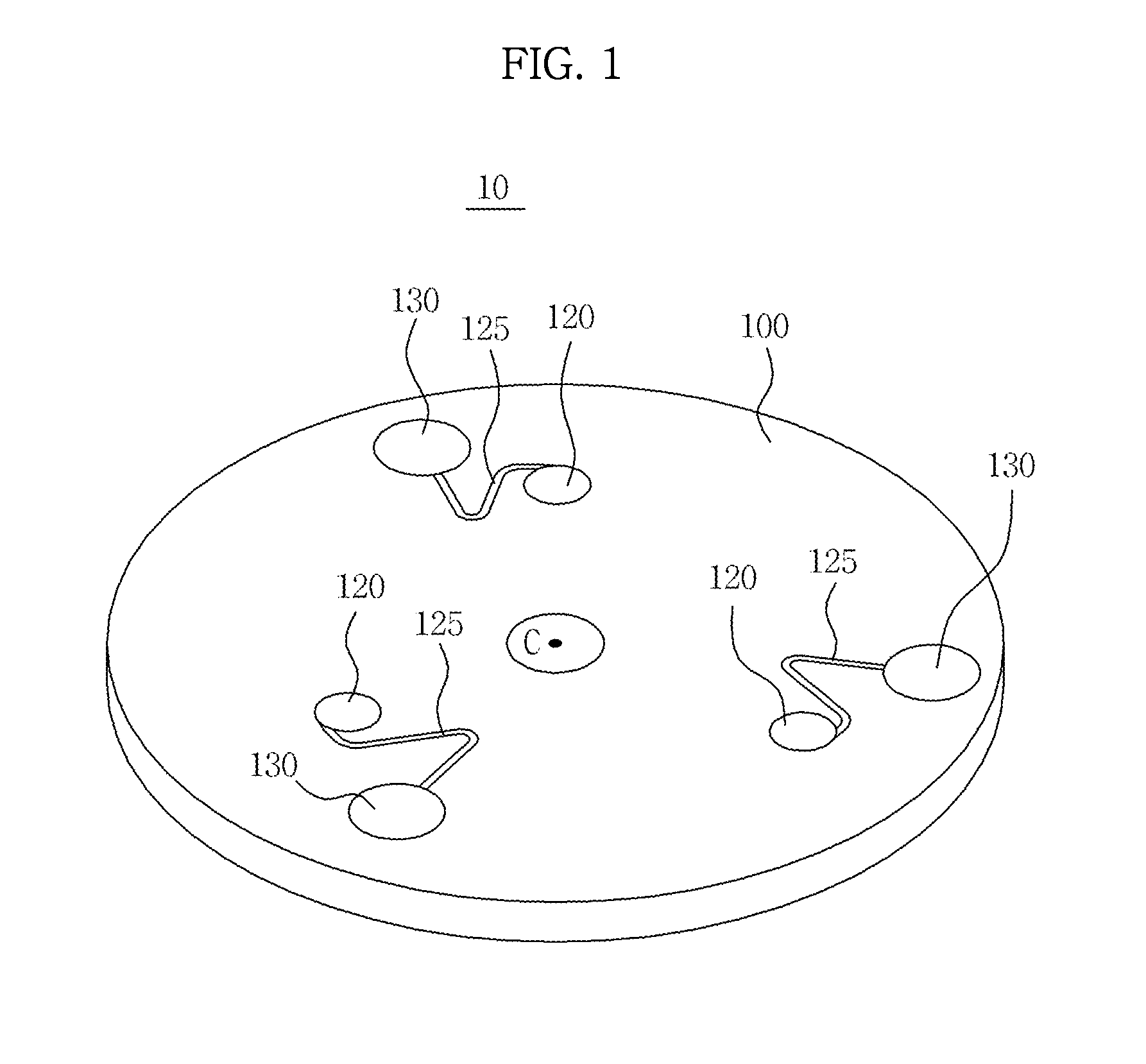
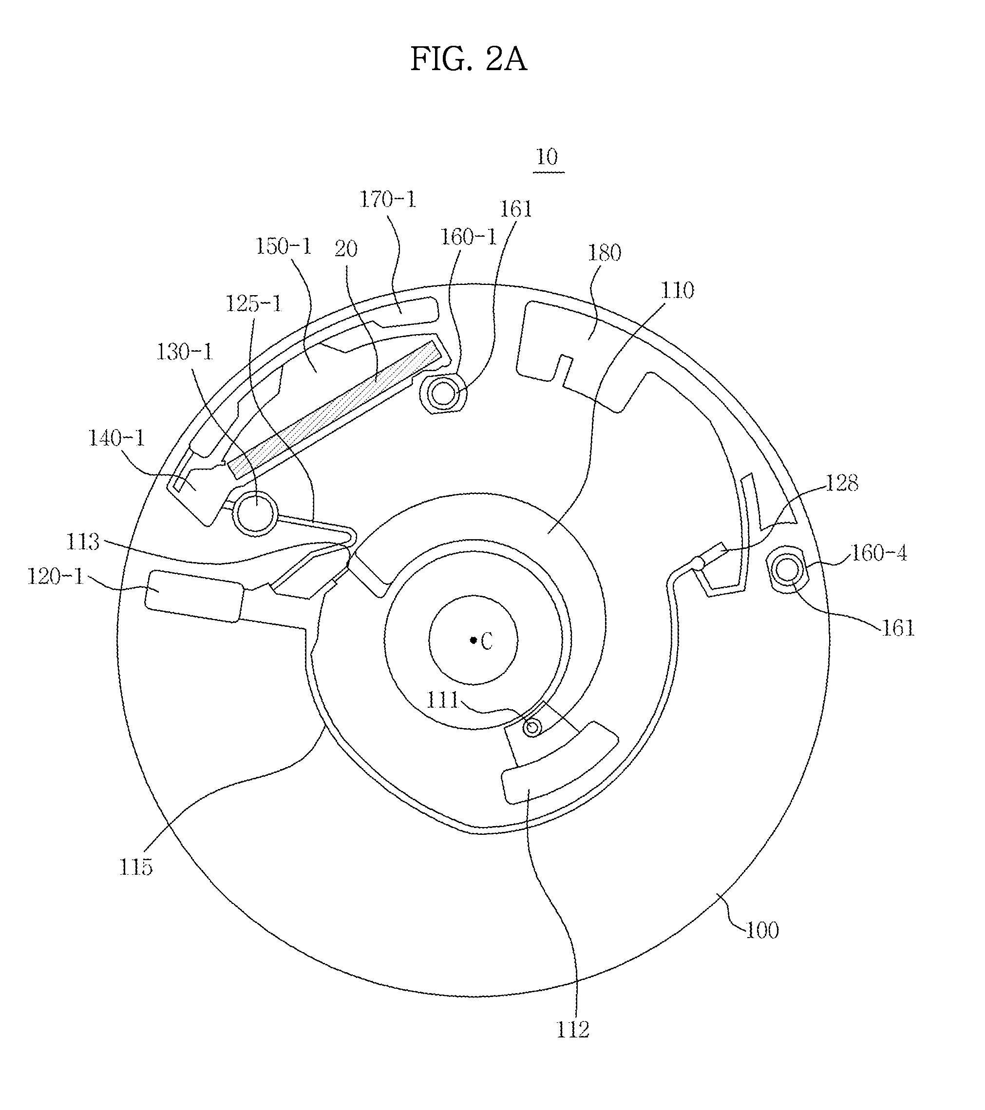
[0059]A microfluidic device according to an exemplary embodiment will be first described, and then a description will be given of a test device, such as a blood testing device, to detect a result of a biochemical reaction occurring on a detection object of the microfluidic device.

[0060]For the test device, a structure and control method of seating the microfluidic device in the test device will be first described and a detection module to detect the detection object positioned at various radii on the microfluidic device will be described, and finally a description will be given of a method of detecting the detection object while maintaining uniform brightness of the detection object to reduce variation in detection results of the detection object.

[0061]A microfluidic device according to an


PUM


Abstract

A test device to detect a detection object of a microfluidic device and a control method thereof are provided. The test device includes a light emitting element configured to emit light onto the microfluidic device, a light receiving element configured to capture an image of the detection object through light emitted from the light emitting element, and a controller configured to determine a signal value of a predetermined area of the image of the detection object, and adjust an exposure level of the light receiving element according to a difference between the signal value and a predetermined target value.

Description


Claims


Application Information

Patent Timeline
Owner SAMSUNG ELECTRONICS CO LTD
Why Eureka
Try Eureka