Panel Display Device, Back Frame and Manufacuring of Back Frame
- Summary
- Abstract
- Description
- Claims
- Application Information
AI Technical Summary
Benefits of technology
Problems solved by technology
Method used
Image

Examples
first embodiment
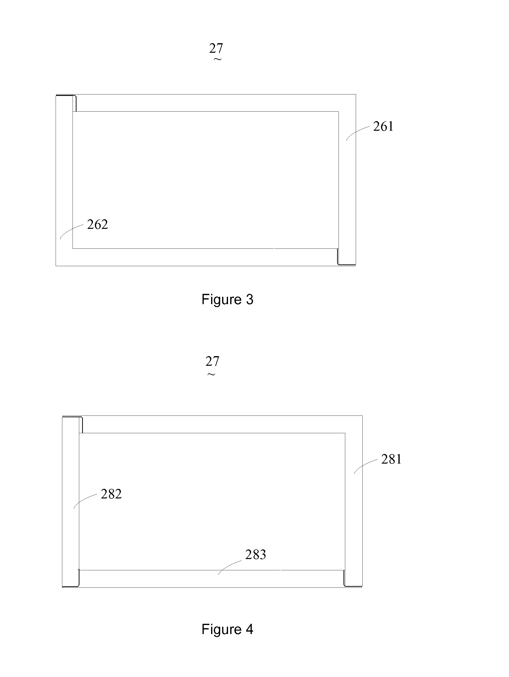
[0055]Also refer to FIG. 3. back frame 23 comprises: a first main splicing element 261 and a second main splicing element 262. One end of first main splicing element 261 is spliced with one end of second main splicing element 262, and the other end of first main splicing element 261 is spliced with the other end of second main splicing element 262 to form main frame 27 of back frame 23. Both first main splicing element 261 and second main splicing element 262 are made of aluminum or galvanized steel. In the present embodiment, both first main splicing element 261 and second main splicing element 262 are L-shaped.
second embodiment
[0056]Also refer to FIG. 4. back frame 23 comprises: a first main splicing element 281, a second main splicing element 282 and a third main splicing element 283. First main splicing element 281, second main splicing element 282 and third main splicing element 283 are spliced to form main frame 27 of back frame 23. First main splicing element 281, second main splicing element 282 and third main splicing element 283 are all made of aluminum or galvanized steel. In the present embodiment, first main splicing element 281 is L-shaped, and both second main splicing element 282 and third main splicing element 283 have a long strip shape.
[0057]In addition, back frame 23 can also comprises two auxiliary splicing elements disposed inside and spliced with main frame 27.
[0058]The following uses four main splicing elements and two auxiliary splicing elements to describe back frame 23 of panel display device 20 of the present invention.
fourth embodiment
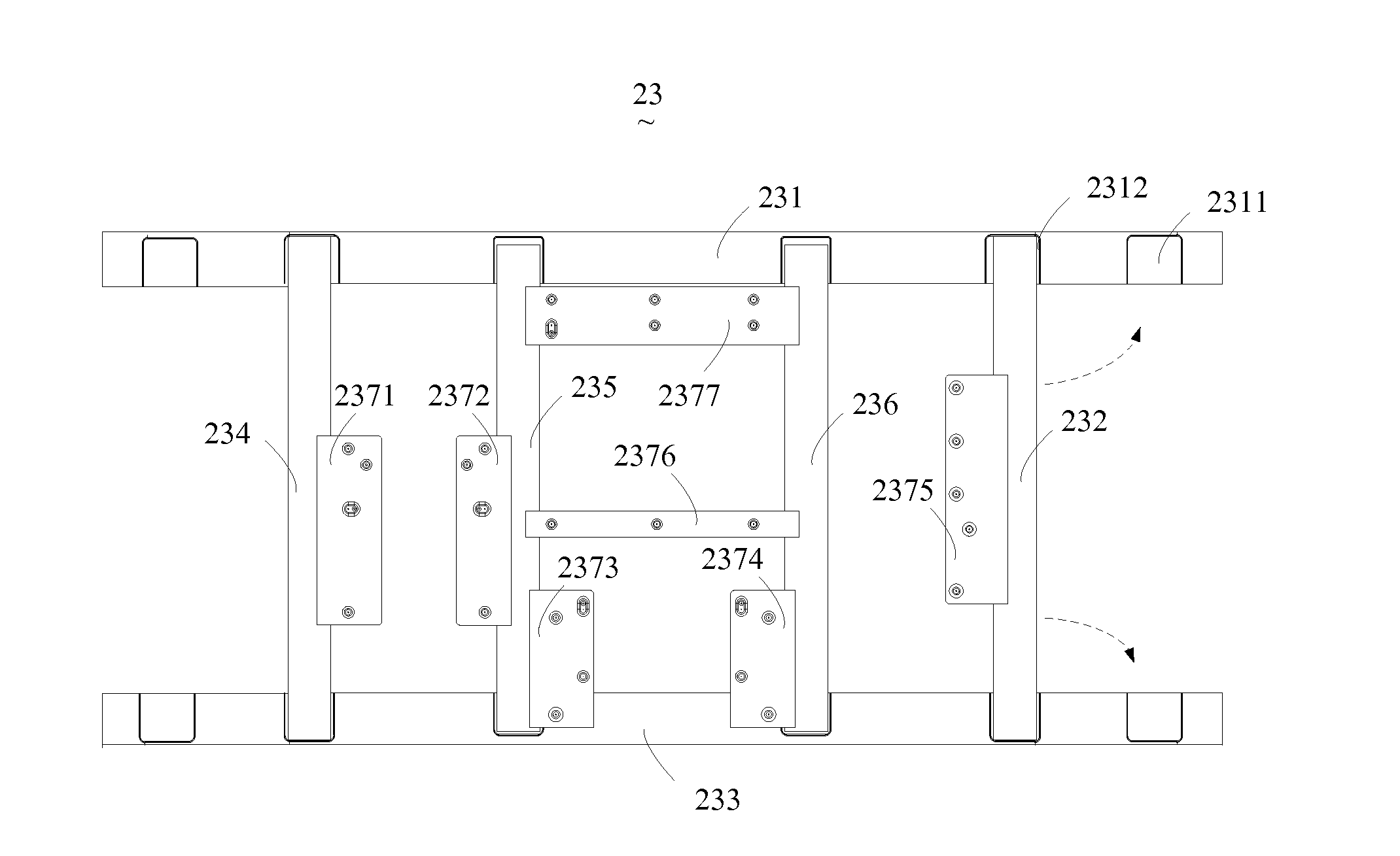
[0059]Referring to FIG. 5, FIG. 5 is a schematic view showing the structure of the panel display device according to the present invention. As shown in FIG. 5, in the instant embodiment, back frame 23 comprises: first main splicing element 231, second main splicing element 232, third main splicing element 233, fourth main splicing element 234, first auxiliary splicing element 235, second auxiliary splicing element 236 and support frame 2371, 2372, 2373, 2374, 2375, 2376, 2377. First main splicing element 231, second main splicing element 232, third main splicing element 233 and fourth main splicing element 234 are spliced in a head-to-tail manner to from main frame 27 of back frame 23. First auxiliary splicing element 235 and second auxiliary splicing element 236 are auxiliary splicing elements, disposed inside main frame 27 and spliced to main frame 27.
[0060]Specifically, one end of first main splicing element 231 is spliced to one end of second main splicing element 232; the other en
PUM
| Property | Measurement | Unit |
|---|---|---|
| Length | aaaaa | aaaaa |
| Size | aaaaa | aaaaa |
Abstract
Description
Claims
Application Information
 - R&D Engineer
- R&D Manager
- IP Professional
- Industry Leading Data Capabilities
- Powerful AI technology
- Patent DNA Extraction
Browse by: Latest US Patents, China's latest patents, Technical Efficacy Thesaurus, Application Domain, Technology Topic.
© 2024 PatSnap. All rights reserved.Legal|Privacy policy|Modern Slavery Act Transparency Statement|Sitemap