Nozzle repairing method and nuclear reactor vessel
- Summary
- Abstract
- Description
- Claims
- Application Information
AI Technical Summary
Benefits of technology
Problems solved by technology
Method used
Image

Examples
first embodiment
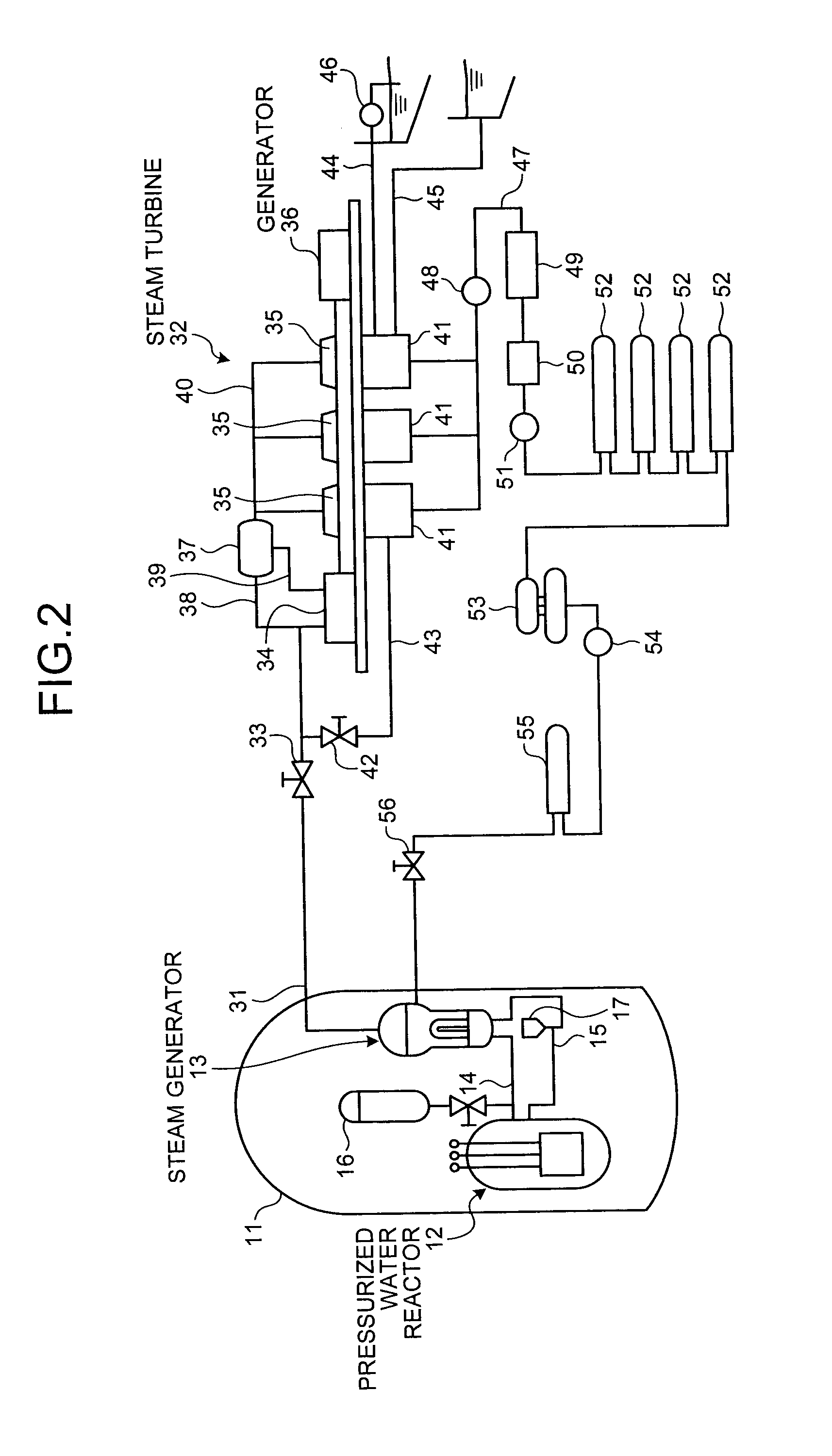
[0038]FIG. 2 is a schematic configuration diagram of a nuclear power plant, and FIG. 3 is a longitudinal sectional view illustrating a pressurized water reactor.
[0039]A nuclear reactor of the embodiment is a pressurized water reactor (PWR) which uses light water as a nuclear reactor coolant and a neutron moderator, adjusts the water to be high-temperature and high-pressure water throughout the entire reactor core so that the light water is not boiled, sends the high-temperature and high-pressure water to a steam generator so as to generate steam by the heat exchange therebetween, and sends the steam to a turbine generator so as to generate electric power.
[0040]In the nuclear power plant with the pressurized water reactor of the embodiment, as illustrated in FIG. 2, a containment 11 accommodates a pressurized water reactor 12 and a steam generator 13, where the pressurized water reactor 12 and the steam generator 13 are connected to each other through a high temperature side feeding tub
second embodiment
[0087]FIG. 19 is a flowchart illustrating a nozzle repairing method according to a second embodiment of the invention, FIG. 20 is a schematic diagram illustrating an operation of removing the upper reactor core internal structure from the nuclear reactor vessel, FIG. 21 is a schematic diagram illustrating a thimble tube cutting operation, FIG. 22 is a schematic diagram illustrating an operation of suspending the lower reactor core internal structure from the nuclear reactor vessel, FIG. 23 is a schematic diagram illustrating an operation of installing the thimble stand in the nuclear reactor vessel, and FIG. 24 is a schematic diagram illustrating a thimble tube supporting operation.
[0088]As in the first embodiment, the nozzle repairing method of the second embodiment includes removing the connection portion with respect to the in-core instrument tube in the groove-welding portion, removing the in-core instrument tube from the lower mirror 66, removing the groove-welding portion and pro
PUM
| Property | Measurement | Unit |
|---|---|---|
| Corrosion resistance | aaaaa | aaaaa |
Abstract
Description
Claims
Application Information
 - R&D Engineer
- R&D Manager
- IP Professional
- Industry Leading Data Capabilities
- Powerful AI technology
- Patent DNA Extraction
Browse by: Latest US Patents, China's latest patents, Technical Efficacy Thesaurus, Application Domain, Technology Topic.
© 2024 PatSnap. All rights reserved.Legal|Privacy policy|Modern Slavery Act Transparency Statement|Sitemap